ServiceInstruction_Vision XP.pdf - 第120页
Page 1 16 Vision XP+ V AC 3 Setup Instructions 3.17 T eaching of Ultrasonic Sensor Inlet and Outlet Operating Instructions V ersion 1.5 Note! The sensor a t th e outlet ist taught with the same procedure. The sensor ist …
Vision XP+ VAC Page 115
3 Setup Instructions
3.17 Teaching of Ultrasonic Sensor Inlet and Outlet
Operating Instructions
Version 1.5
3.17 Teaching of Ultrasonic Sensor Inlet and Outlet
In order the obtain the correct switching point of the ultrasonic sensor it has
tube calibrated by means of the teaching procedure. Example at the inlet.
Note!
If the system is equipped with a dual-lane conveyor, the same procedure is
used for both lanes.
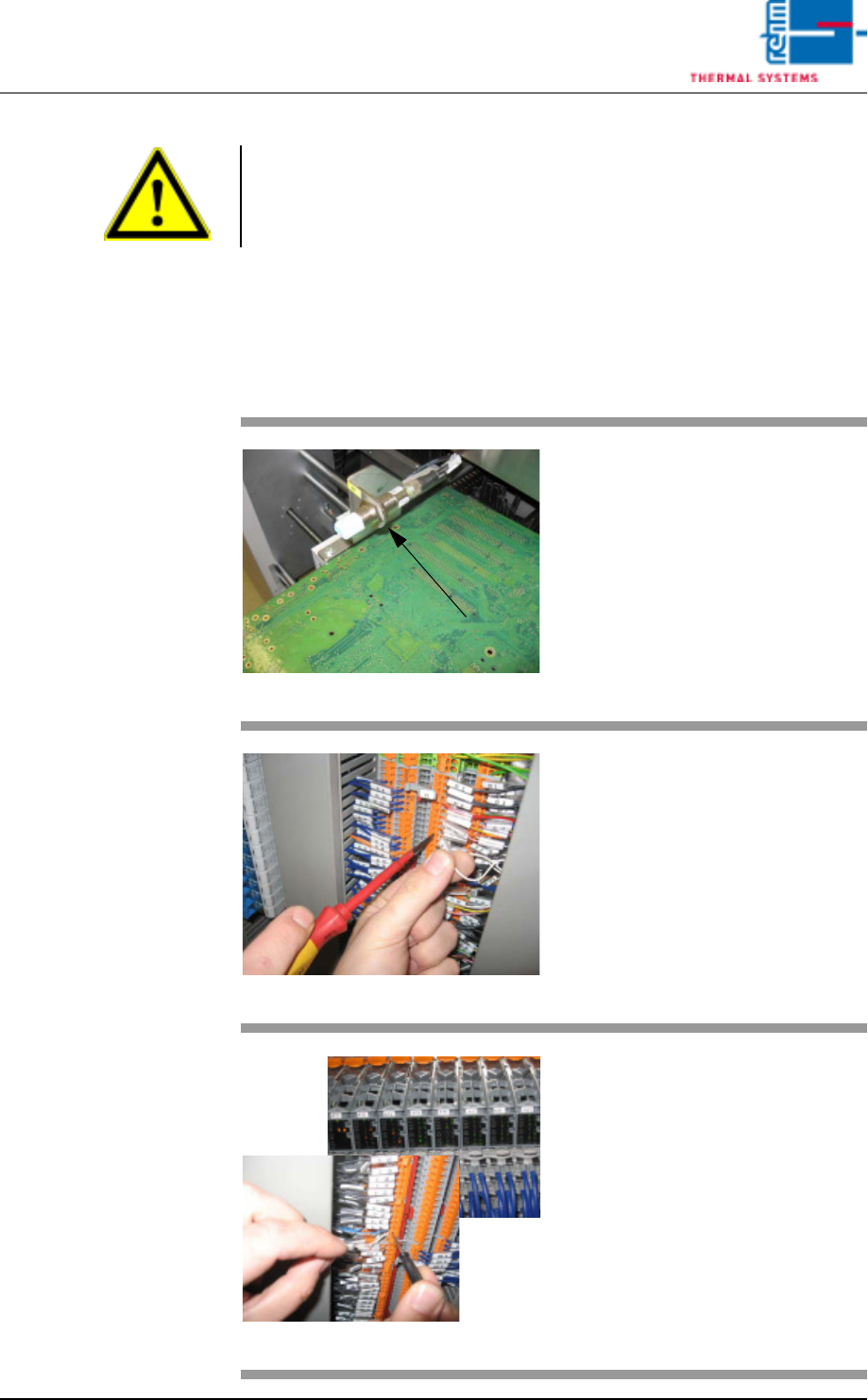
Fig. 3-25 Ultrasonic senor
Put one PCB over the conveyor
onto the conveyor rails sot that the
sensor is covered
Fig. 3-26 Terminal X1
Open the switch cabinet door
behind which the terminal block X1
is located (see the wiring diagram
white wire).
Fig. 3-27 X- terminal and SPS
Remove the white wire of the light
barrier (WB1) from the
open-circuited terminal.
Hold for >3 sec. onto the X-terminal.
Now, the ultrasonic sensor is
flashing twice.
When the ultrasonic sensor
(SPS- entry) doesn't flash any
more, clamp the white wire again
into the blank terminal.

Page 116 Vision XP+ VAC
3 Setup Instructions
3.17 Teaching of Ultrasonic Sensor Inlet and Outlet
Operating Instructions
Version 1.5
Note!
The sensor at the outlet ist taught with the same procedure. The sensor ist
connected on the X1 terminal board.
Vision XP+ VAC Page 117
3 Setup Instructions
3.18 Exhaust Air Monitoring
Operating Instructions
Version 1.5
3.18 Exhaust Air Monitoring
Prerequisites:
• The plant exhaust system must be switched on and operating at full
power.
• The plant exhaust system must be properly maintained and clean.
• The system must be switched on.
The press switch is located at the inlet on the back side of the machine.
Inspection
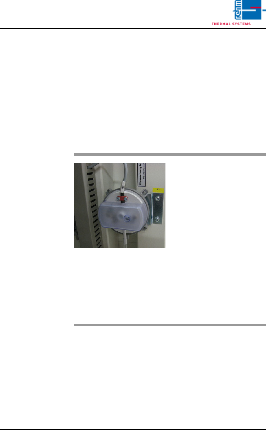
Fig. 3-28 Exhaust Air Differential Pressure
Gauge
Procedure:
1. Unscrew the cover from the
pressure switch.
2. As long as the plant exhaust
system is switched on, the air
exhaust alarm status in the
alarm window must be green
(OK). If this is not the case, the
pressure capsule must be read-
justed.
3. Carefully pull the tube from the
capsule and check to see
whether or not the exhaust
alarm is displayed in red. If no
alarm is displayed, the pressure
capsule must be adjusted.
4. Reconnect the tube.
5. Remount the protective cover
after inspection and adjustment
have been completed.