ServiceInstruction_Vision XP.pdf - 第136页
Page 132 Vision XP+ V AC 3 Setup Instructions 3.22 Default V alues Operating Instructions V ersion 1.5
Vision XP+ VAC Page 131
3 Setup Instructions
3.22 Default Values
Operating Instructions
Version 1.5
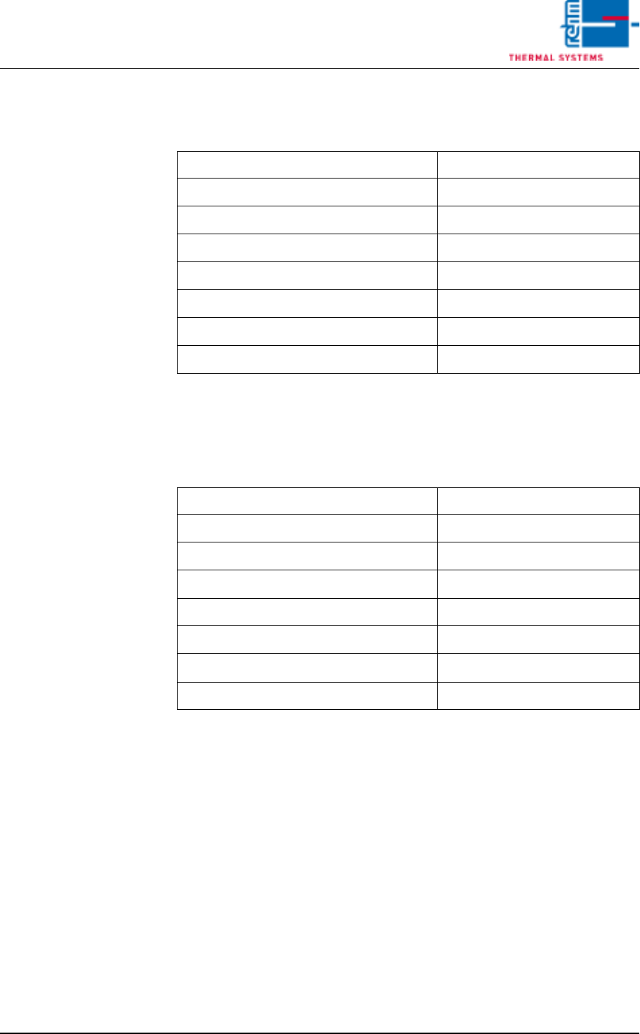
3.22.10 Default Values Consumption Parameters
Tab. 3-14 Default Value Consumption Parameters
3.22.11 Default Values Filter F9 Parameter
Tab. 3-15 Default Values Filter F9 Parameter
Consumption Parameters Value
Converter proportion of power
30
Pulses per kWh
10000
Analog Value Minimal Value
300 digits
Real Minimal Value
0 l/min
Analog Value Maximum Value
32700 digits
Real Maximum Value
1000 l/min
N² Consumption limit max.
50 m³/h
Filter F9 Parameter Value
Analog Value Minimal Value
50 digits
Real Minimal Value
0 Pa
Analog Value Maximal Value
32760 digits
Real Maximal Value
250 Pa
Limit max. 1
120 Pa
Limit max. 2
140 Pa
Measuring Frequency
40 Hz

Page 132 Vision XP+ VAC
3 Setup Instructions
3.22 Default Values
Operating Instructions
Version 1.5

VISION XP+ VAC Page 133
Page
List of Figures
Operating Instructions
Version 1.5
List of Figures
Volume flow control, cooling section parameter Fig. 3-14 98
Additional cleaning chute Fig. 2-34 28
Adjusting the Center Support Fig. 3-24 114
Adjusting the Conveyor Side Panel Fig. 3-23 112
Alarm Configuration Fig. 3-9 81
Bottom Curtains Fig. 2-17 22
Chain lubricating pumps with two and one outlet Fig. 2-98 57
Chain Lubricator Fig. 3-8 80
Chain oiler - MU (bottom) Fig. 2-100 58
Changing to adjusting plane Fig. 3-17 103
Check the chain slack Fig. 2-52 37
Checking the Water Fill-Level Fig. 2-67 45
Cleaning of coated nozzle fields Fig. 2-14 20
Cleaning of coated nozzle fields Fig. 2-15 20
cleaning of oven station Fig. 2-4 16
cleaning of oven station Fig. 2-5 16
Cleaning the Fan Impeller Fig. 2-41 30
Cleaning the gas take-off point Fig. 2-88 53
Cleaning the Guide Rails Fig. 2-16 21
Cleaning the Interior Fig. 2-3 15
Cleaning the Process Chamber Seal Fig. 2-20 23
Cleaning the Sensors Fig. 2-101 59
Compressed Air and Nitrogen Unit Fig. 3-32 121
Condensate Trap Layout Fig. 2-70 46
Condensate Trap Fig. 2-69 46
Configuration Activ Energy Meters Fig. 3-22 109
Control Cabinet 1 Fig. 2-102 60
Control Cabinet 2 Fig. 2-103 60
Conveyor Adjustment – Parameters Fig. 3-7 77
Conveyor Drive Parameters Fig. 3-6 75
Coolant Water Regulation Fig. 3-31 120
Cover for Suction Chamber Fig. 2-31 27
Disconnect power supply Fig. 2-36 29
Exchange activated carbon Fig. 2-93 55
Exchange activated carbon Fig. 2-94 55
Exchange activated carbon Fig. 2-95 55
Exchange activated carbon Fig. 2-96 56
Exchange activated carbon Fig. 2-97 56
Exhaust Air Differential Pressure Gauge Fig. 3-28 117
Extracting the nozzle holder Fig. 2-10 18
Extracting the nozzle holder Fig. 2-11 18
Extracting the nozzle holder Fig. 2-12 18
Fan Impeller Fig. 2-33 27
Fan Parameters Fig. 3-11 93
Fans Parameter (example) Fig. 3-33 127
Filter Vacuum pump Fig. 2-57 40
Filter Vacuum pump Fig. 2-58 40
Filter Vacuum pump Fig. 2-59 40
Flux Management Parameters Fig. 3-5 74
Frequency Converter Parameters Fig. 3-10 84