ServiceInstruction_Vision XP.pdf - 第91页
Vision XP+ V AC Page 87 3 Setup Instructions 3.5 Frequency Converter Operating Instructions V ersion 1.5 9. In order to activat e programming, the frequency conver ters must be restarted via t he 3-pole circuit break er …
Page 86 Vision XP+ VAC
3 Setup Instructions
3.5 Frequency Converter
Operating Instructions
Version 1.5
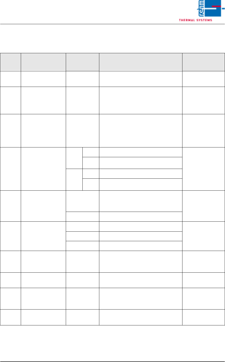
The following table includes all parameters which are set as standard
values.
Tab. 3-2 Parameter Mitsubishi FR-D 700
8. After all entries have been completed, press the Mode key once to
display the alarm list, or twice to return to the monitor display.
Para-
meter Function
Setting
Values Description of Selected Parameter
Setting Value for
this System
79 Operating mode
selection
0 / 1 0: Setpoint specification via PC
1: Set all parameters
1 (during
programming)
160 Display of param-
eters for the ex-
tended function
range
9999 / 0 0: No display / all parameters
9999: Display / basis parameters
Caution! Do not put the value man-
ually to 0. It happens automatically.
0 (during
programming)
117 Station number 1 to 31 If more than one frequency convert-
er is used, communication with the
corresponding converter is estab-
lished by means of the station num-
ber.
x
119
Stop bits / data
bits
8
bits
0 Stop bits: 1
0
1 Stop bits: 2
7
bits
10 Stop bits: 1
11 Stop bits: 2
123 Response time /
waiting time
0 to 150 ms Selection of the waiting time which
elapses from receipt of data until a
response is transmitted. 20
--- Setting with communication data
124
Activate
CR/LF command
0 CR/LF command deactivated
2
1 CR command activated
2 CR/LF command activated
192
A, B, C, terminal
function selection
0
1 frequency
set point
Relay output terminal
1
338 Write operating
instruction
0 / 1 0: Start from serial
1: Start from external
1
340 Select operating
mode with serial
communication
0 / 1 1: Interface operation at power-up 1
79 Operating mode
selection
0 / 1 0: Setpoint specification via PC
1: Set all parameters
1 (during
programming)

Vision XP+ VAC Page 87
3 Setup Instructions
3.5 Frequency Converter
Operating Instructions
Version 1.5
9. In order to activate programming, the frequency converters must be
restarted via the 3-pole circuit breaker.
10. Converter type must be set to 3 in the Frequency Converter
Parameters window in order to execute automatic parameters
configuration.
11. If Continuous Operation appears at the status display, parameters
configuration has been completed. Type must now be changed to 2, and
the system parameters have to be saved to memory.
12. The frequency converter is ready for operation when the PU and EXT
LEDs blink.
Note!
Special settings should only be entered by service technicians from Rehm
Thermal Systems.
Page 88 Vision XP+ VAC
3 Setup Instructions
3.5 Frequency Converter
Operating Instructions
Version 1.5
3.5.2 Typ Mitsubishi FR-D 700
Setting system
parameters
In connection with a Siemens control
Note!
If a signal is upcoming at the clamp „STR or „STF“ the parameter P4 can be
changed all the same.
1. Start with point 2 if the frequency converters 24V are not activated. As
long as the system conveyor is running, a signal is on the „STR or STF“
clamp and the converters are locked for any entry. To change the set-
tings, the „STR“ or „STF“ clamp needs to be disconnected. Stop the fre-
quency converter with the stop button.
2. First set the operating mode to 0, as otherwise the other parameters
cannot be checked or changed.
Press button Mode, on the display any type of parameter is indicated.
Select the parameter P79 with the Digital Dial.
Press button Set and set the value to 0 with the Digital Dial. Press button
Set for confirmation.
Return to the starting position with the button Mode.
3. For changing the parameter settings press the PU/EXT key until the
LED below PU lights up. (Switching over to the PU operation mode is
only possible if the inverter is at a stop).
4. When the Mode key is pressed, P 0 is shown on the display.
5. Press the Set key to read the currently set value for the selected param-
eter.
6. The newly selected value is then saved to memory by activating the Set
key. The display returns once again to the parameters window.
7. The newly selected value is then saved to memory by activating the Set
key. The display returns once again to the parameters window.
8. Steps 5 through 8 must then be repeated if additional parameters need
to be changed.
9. The frequency converter must be returned to the EXT operating mode
by pressing the PU/EXT key in order to exit the parameter setting func-
tion.
10. Operating parameter 79 must once again be set to the value specified
in the table as described in point 2. Re-clamp the triggering STR at the
frequency converter.
The list below shows all parameters which have been set as standard val-
ues.
Attention!
The heaters may not exceed a temperature of 70° C, because the fans
might otherwise overheat.