ServiceInstruction_Vision XP.pdf - 第50页
Page 46 Vision XP+ V AC 2 Maintenance 2.1 1 Condensate T rap Operating Instructions V ersion 1.5 2.1 1 C ondensate T rap 2.1 1.1 Cleaning of Condensate T rap VXP+ (option) Fig. 2-6 9 Con densate Trap Fig. 2-7 0 Con densa…
Vision XP+ VAC Page 45
2 Maintenance
2.10 Water Tank - Checking and Refilling the Water
Fill-Level (Option)
Operating Instructions
Version 1.5
2.10 Water Tank - Checking and Refilling the Water Fill-Level (Op-
tion)
Fig. 2-67 Checking the Water Fill-Level
Fig. 2-68 Checking the Water Fill-Level, CN
The water tank is located behind the
second door from the right.
Consumable materials, tools:
• Water
• Antifreeze
Note!
Coolant is mixed using 1 part an-
tifreeze to 3 parts water.
• Watering can or similar container
Procedure:
1. The front of the water tank is
marked with the designations
MAX. and MIN.
2. When the fill-level drops to the
minimum mark, the tank must
be refilled with coolant to the
maximum mark.
3. For re-filling open the filling port
(D) at the tank and fill in the
mixed cooling liquid.
Cooling system components:
A) Cooling water controller
B) Water leak and minimum water
level sensor
C) Connection for draining water
D) Filling port
E) Temperature watchdogs
A
B
C
D
E
A
C
E
B
D
Page 46 Vision XP+ VAC
2 Maintenance
2.11 Condensate Trap
Operating Instructions
Version 1.5
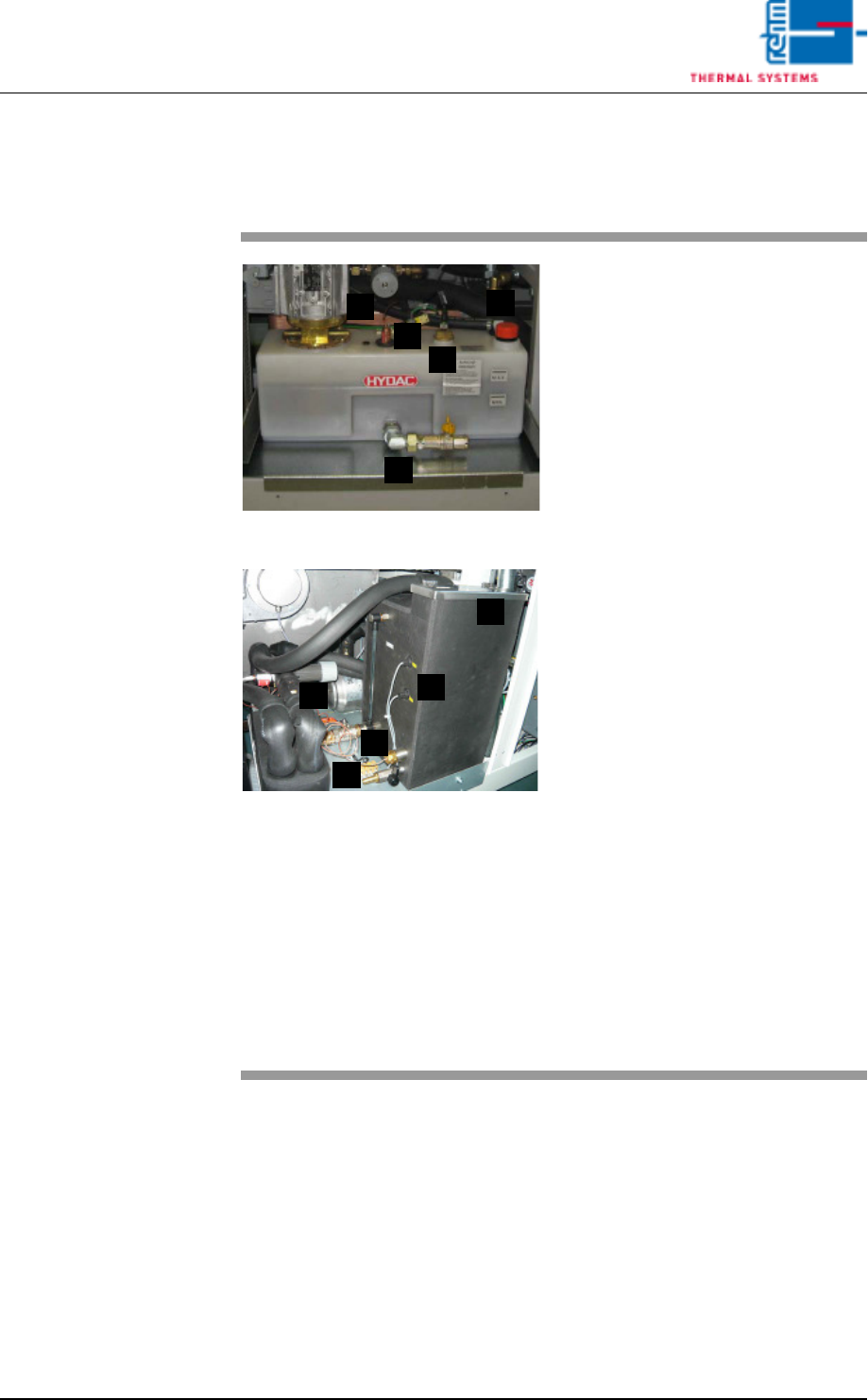
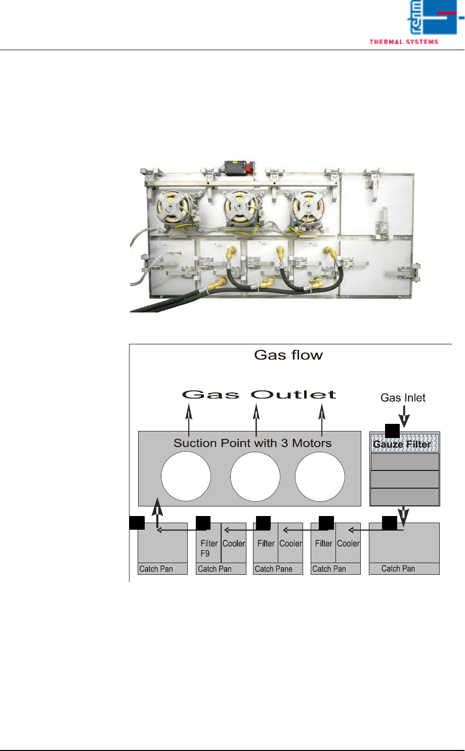
2.11 Condensate Trap
2.11.1 Cleaning of Condensate Trap VXP+ (option)
Fig. 2-69 Condensate Trap
Fig. 2-70 Condensate Trap Layout
Make sure that the following conditions have been fulfilled before working on
the condensate trap:
• Make sure that the fans are switched off and that water pressure has been
relieved with the help of the software. The “Cooling Tract Stopped” mes-
sage must appear at the monitor screen and the lock must be opened. Re-
fer to the “Main Window” subsection of the “Software” chapter in the
operating instructions to this end.
• Undo the water connections.
A
D C C BB
Vision XP+ VAC Page 47
2 Maintenance
2.11 Condensate Trap
Operating Instructions
Version 1.5
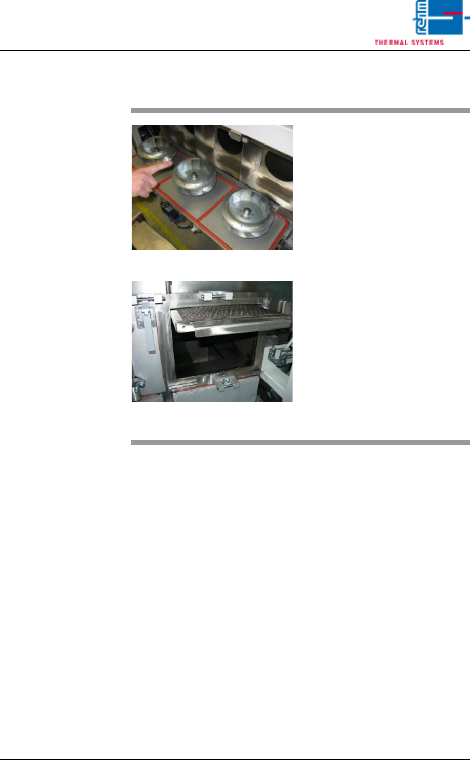
2.11.2 Clean the suction ducts and the Gauze Filter (A)
Fig. 2-71 Pulling Out the Gauze Filter
Fig. 2-72 Pulling out of the Gauze Filter
Wipe out the suction ducts behind
the fan wheels with the oven clean-
er.
The Gauze Filter are located in the
suction duct on the right side of the
Condensation Trap (see Fig. 2-22,
point A).
Consumable materials, tools:
• Oven cleaner
• Rags
• Rinsing bath
Procedure:
1. Pull the gauze filter out and set
it into a rinsing bath.
2. Clean the opening for the gauze
filter next to the condensate
trap with oven cleaner and rags.
3. Reinsert the cleaned gauze fil-
ter.