ServiceInstruction_Vision XP.pdf - 第17页
Vision XP+ V AC Page 13 2 Maintenance 2.3 Mainten ance Schedule Operating Instructions V ersion 1.5 T ab. 2-1 Mainten ance Sc hedule Nit ro Control cabinets V acuuming and cleaning x 10 min V acuum cleaner Fan covers V a…

Page 12 Vision XP+ VAC
2 Maintenance
2.3 Maintenance Schedule
Operating Instructions
Version 1.5
Cooling zone 1
(VXP)
Cleaning cooling
zone 1
x 1 min If neces-
sary
2 min
Inlet Inspection of inlet
filter, cleaning if
necessary
x 1 min If neces-
sary
2 min
Check Sensor and
cleaning if neces-
sary
x 1 min If neces-
sary
2 min
Inlet exhaust Inspection of con-
tainer, connecting
pieces and throttle
cleaning if neces-
sary
x 1 min If neces-
sary 5
min
Outlet Inspection of out-
let filter, cleaning if
necessary
x 1 min If neces-
sary
2 min
Outlet exhaust Inspection of con-
tainer, connecting
pieces and throttle
valve cleaning if
necessary
x 1 min If neces-
sary 5
min
Pyrolysis Replacement of
granulate, seals
x 2 h Granulate,
seals
Gas take-off
point
Cleaning of gas
take-off point
x 1 min 5 min Hex key,
Cleaning
rag
Analyzer Pre-filter ex-
change
x indi-
cated
5 min Activated
carbon filter
Activated carbon
exchange
x indi-
cated
5 min Activated
carbon
Conveyor sys-
tem
Inspection of
chain oil fill level
x 1 min 2 min Chain oil
Inspection of
chain tension
x 10
min
30 min
if neces-
sary
Chain oil
Sensors checking x 1 min 2 min
water tank Inspection of wa-
ter tank fill level if
necessary refill
x 1 min If neces-
sary 3
min
water, anti-
freeze
Sector Maintenance task
(inspection, cleaning
and replacement of
parts if necessary)
Daily
Weekly
Fortnightly
Monthly
Quarterly
Semiannually
Annually
Inspection Time
Maintenance Time
Replacement
Recommend-
ed Parts and
Materials

Vision XP+ VAC Page 13
2 Maintenance
2.3 Maintenance Schedule
Operating Instructions
Version 1.5
Tab. 2-1 Maintenance Schedule Nitro
Control cabinets Vacuuming and
cleaning
x 10 min Vacuum
cleaner
Fan covers Vacuuming and
cleaning
x 2 min 5 min Vacuum
cleaner
Complete sys-
tem
Electrical safety
check by safety
specialist
x 2 h
Complete mainte-
nance check by
Rehm Thermal
Systems
x 8 h Due to wear
Sector Maintenance task
(inspection, cleaning
and replacement of
parts if necessary)
Daily
Weekly
Fortnightly
Monthly
Quarterly
Semiannually
Annually
Inspection Time
Maintenance Time
Replacement
Recommend-
ed Parts and
Materials
Page 14 Vision XP+ VAC
2 Maintenance
2.4 Inlet
Operating Instructions
Version 1.5
2.4 Inlet
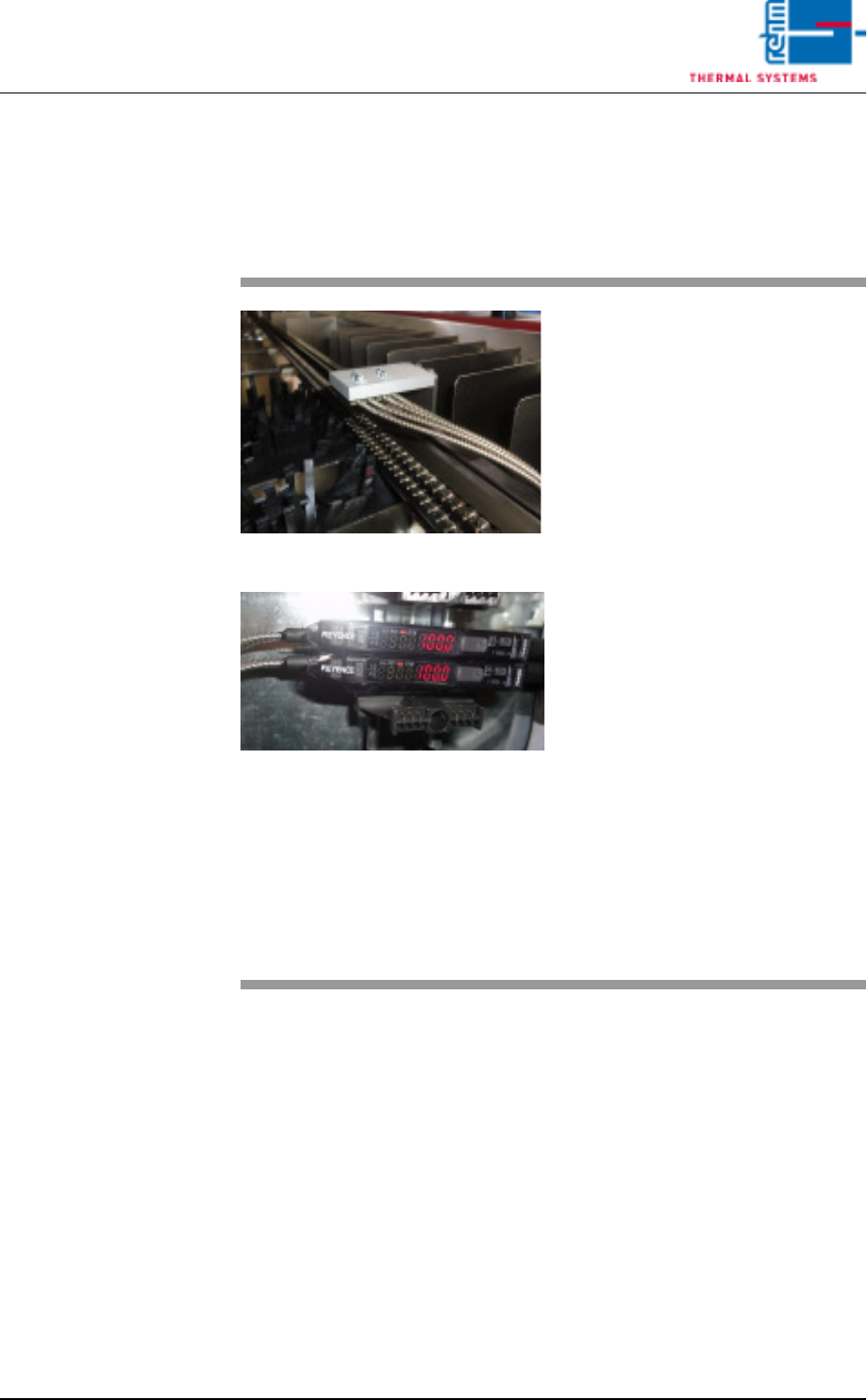
2.4.1 Optical fibre sensor at the inlet area
Fig. 2-1 Optical fibre sensor at the inlet
Fig. 2-2 Optical fibre sensor at the inlet
The plant has an optical fibre sensor
at its inlet. This optical fibre sensor
is used for PC board identification.
The specified set-point value of this
sensor is between
100 - 250 digits.
Rehm Thermal Systems techni-
cians preset the switching threshold
to 350 digits for a single track and
500 digits for a dual track.
The PC board will be detected when
the threshold level is exceeded.
The degree of soiling is determined
as a percentage. An alarm will in ad-
dition be triggered in the display
should this approach the threshold
level.
To continue proper operation, the
sensor should then be cleaned as
soon as possible, using an appropri-
ate cleaning agent.
The settings are based on Rehm
Thermal Systems experience.