ServiceInstruction_Vision XP.pdf - 第21页
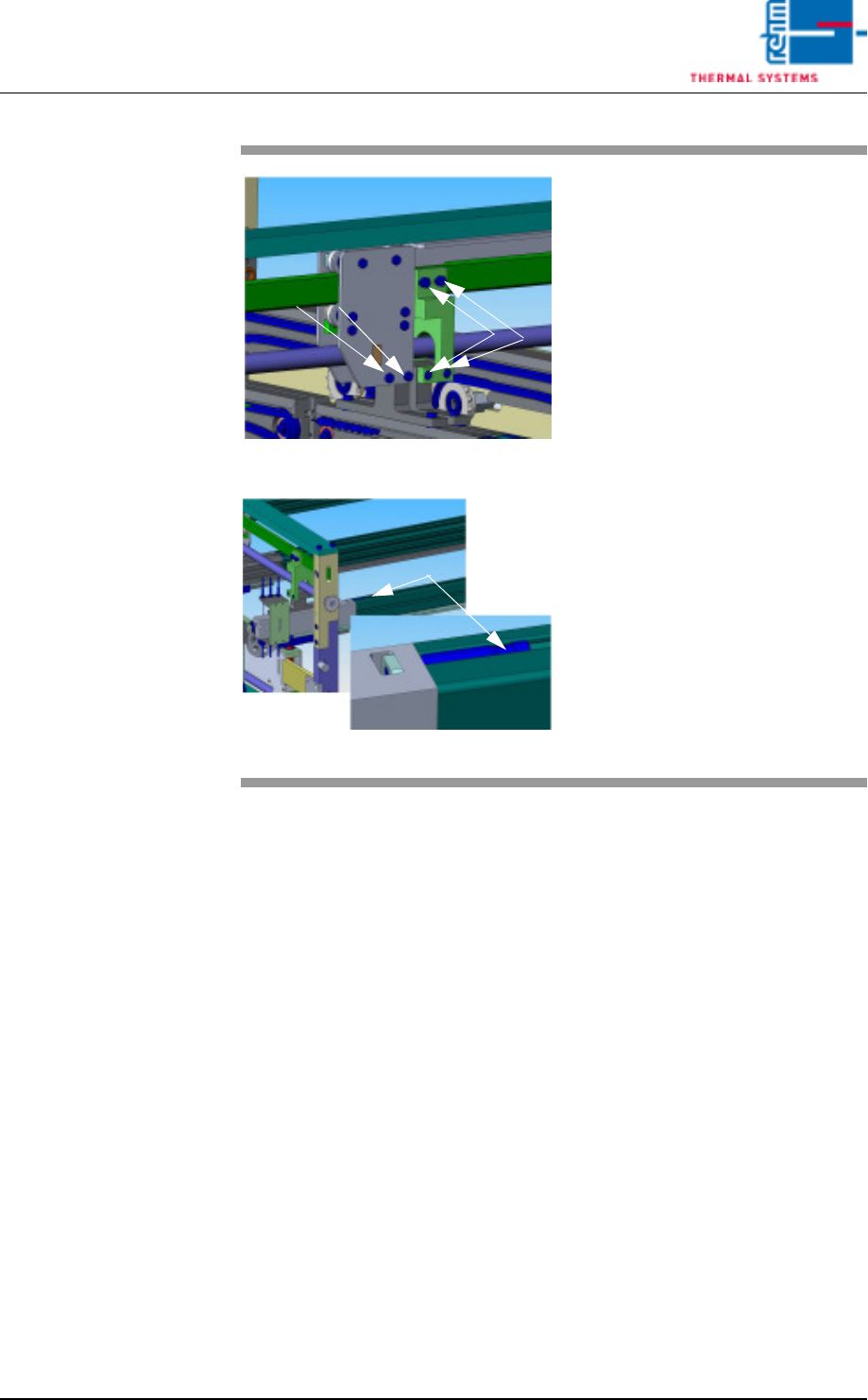
Vision XP+ V AC Page 17 2 Maintenance 2.5 Process chamber Operating Instructions V ersion 1.5 Fig. 2-7 Oven station CA D 1 Fig. 2-8 Oven station CA D2 6. The screws shown m ust also be checked and retightened as nec- ess…
Page 16 Vision XP+ VAC
2 Maintenance
2.5 Process chamber
Operating Instructions
Version 1.5
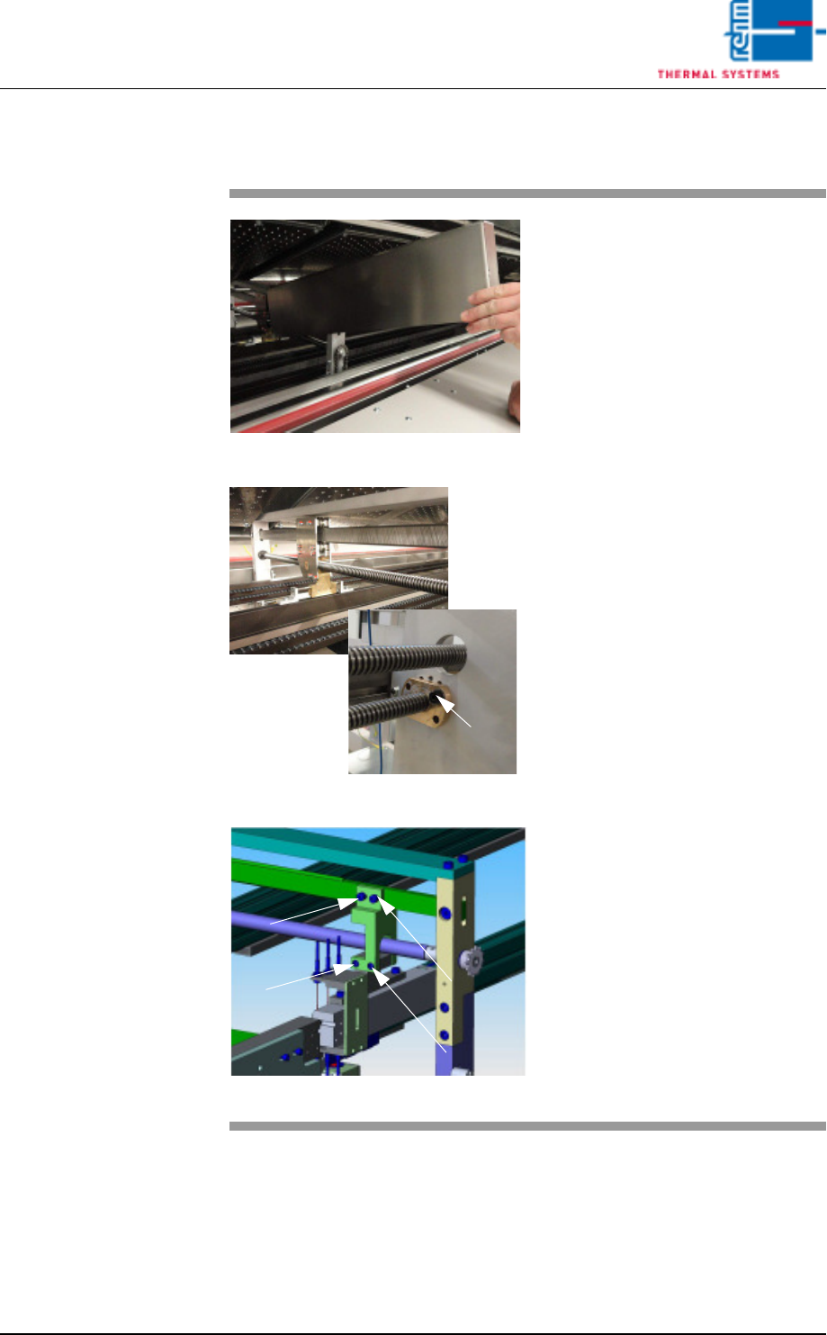
2.5.2 Cleaning of oven stations
Fig. 2-4 cleaning of oven station
Fig. 2-5 cleaning of oven station
Fig. 2-6 Oven station CAD
Expendable materials:
• Oven cleaning agent
• Cleaning cloths
• Paint brush
• Chain oil Addinol
Procedure:
1. Remove the cover of the oven
station.
2. Clean spindles from the PCB and
CBS width adjustment at the inlet
and the outlet as well as the oven
stations with cleaning cloths and
oven cleaning agent.
3. Oil the spindles with the paint
brush after the cleaning.
4. Check the spindle nut regularly
for „clearance“.
5. This oven station picture (CAD)
shows the screws to regularly
check and retighten as neces-
sary.
Spindle nut
Vision XP+ VAC Page 17
2 Maintenance
2.5 Process chamber
Operating Instructions
Version 1.5
Fig. 2-7 Oven station CAD 1
Fig. 2-8 Oven station CAD2
6. The screws shown must also be
checked and retightened as nec-
essary.
7. Checking and, if necessary,
retightening may also be required
here.
Page 18 Vision XP+ VAC
2 Maintenance
2.5 Process chamber
Operating Instructions
Version 1.5
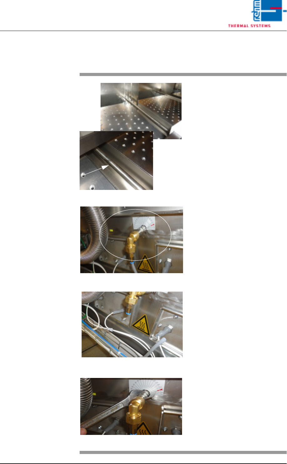
2.5.3 Cleaning the nozzle holder (VXP+)
Fig. 2-9 Nozzle holder
Fig. 2-10 Extracting the nozzle holder
Fig. 2-11 Extracting the nozzle holder
Fig. 2-12 Extracting the nozzle holder
Consumable:
• Oven cleaner
• Cleaning rags
• 1 mm drill
• 22-er flat spanner
Procedure:
1. The nozzle holder connection is
at the back of the machine. Re-
move the complete nozzle hold-
er pipe here for easier cleaning.
2. First remove the Festo hose
whilst cold.
3. Use a 22 mm flat spanner to
loosen the nuts. Now pull out
the nozzle holder pipe.