ServiceInstruction_Vision XP.pdf - 第72页
Page 68 Vision XP+ V AC 3 Setup Instructions 3.2 T emperature Channels Operating Instructions V ersion 1.5 B) ta Set sampling time (only relevant wi th B&R controller) C) Kp Proportional com ponent for the PID contro…
Vision XP+ VAC Page 67
3 Setup Instructions
3.2 Temperature Channels
Operating Instructions
Version 1.5
AD)Last field module fault
Last fault displayed. Info for servicing purposes.
3.2 Temperature Channels
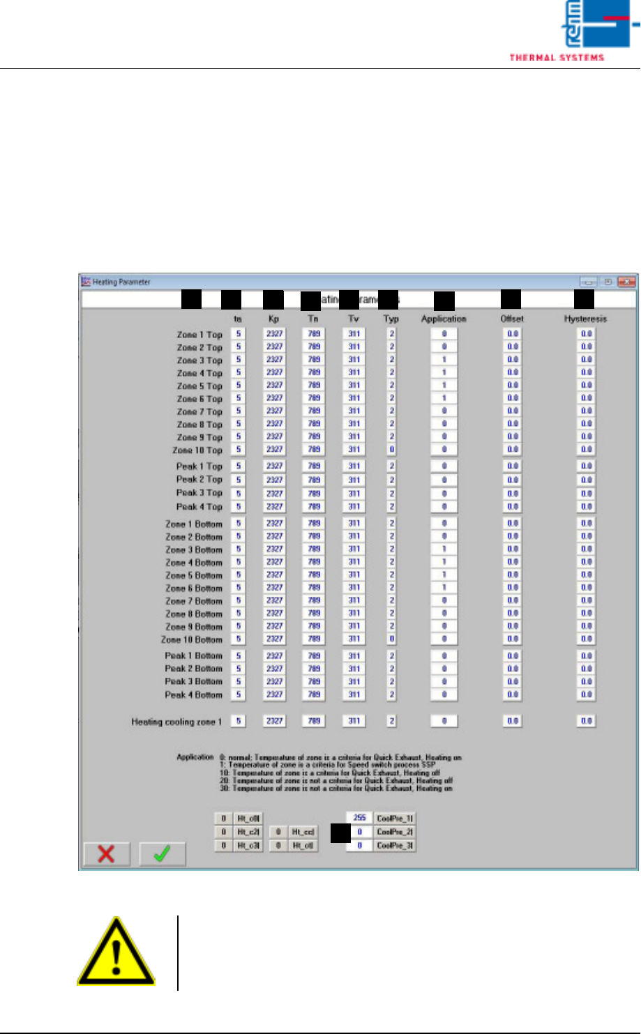
3.2.1 Heater Parameters
Fig. 3-3 Heater Parameters
A) Designations of the individual heat zones
F
D
B
A
C E
G
H I
J
Caution!
Values are system-specific and may only be changed by service personnel
from Rehm Thermal Systems GmbH!
This value may only be changed when heat is turned off.
Page 68 Vision XP+ VAC
3 Setup Instructions
3.2 Temperature Channels
Operating Instructions
Version 1.5
B) ta
Set sampling time (only relevant with B&R controller)
C) Kp
Proportional component for the PID controller
Default setting: for B&R controller: 2327
for S7 controller: 8
D) Tn
Integral component for the PID controller
Default setting: for B&R controller: 789
for S7 controller: 150
E) Tv
Differential component for the PID controller
Default setting: for B&R controller: 311
for S7 controller: 120
F) Type
This value must be set to 2 for one control channel. One open input must
be set to 0.
G) Application
With the Quick Cooling Down (SSP) you have to enter 1 in all zones
where cooling pipes are installed.
The Quick Exhaust behaves with the setting 0 as before (from Software
V3.14).
Over the values 10 a. 20 the behavior can be configured (corresponding
to the settings 1 and 2 with Software V3.13 and earlier).
H) Offset
Deviation at the temperature display can be compensated for with the
offset function.
I) Hysteresis
Tolerance evaluation performance can be adapted with the hysteresis
function.
J) Here you can adjust, which zone should be cooled down
Default values
CoolPre_1 = 255 (cooling last pre-heating zone)
CoolPre_2 = 0 (cooling zone 1 top)
CoolPre_3 = 0 (cooling zone 2 top)
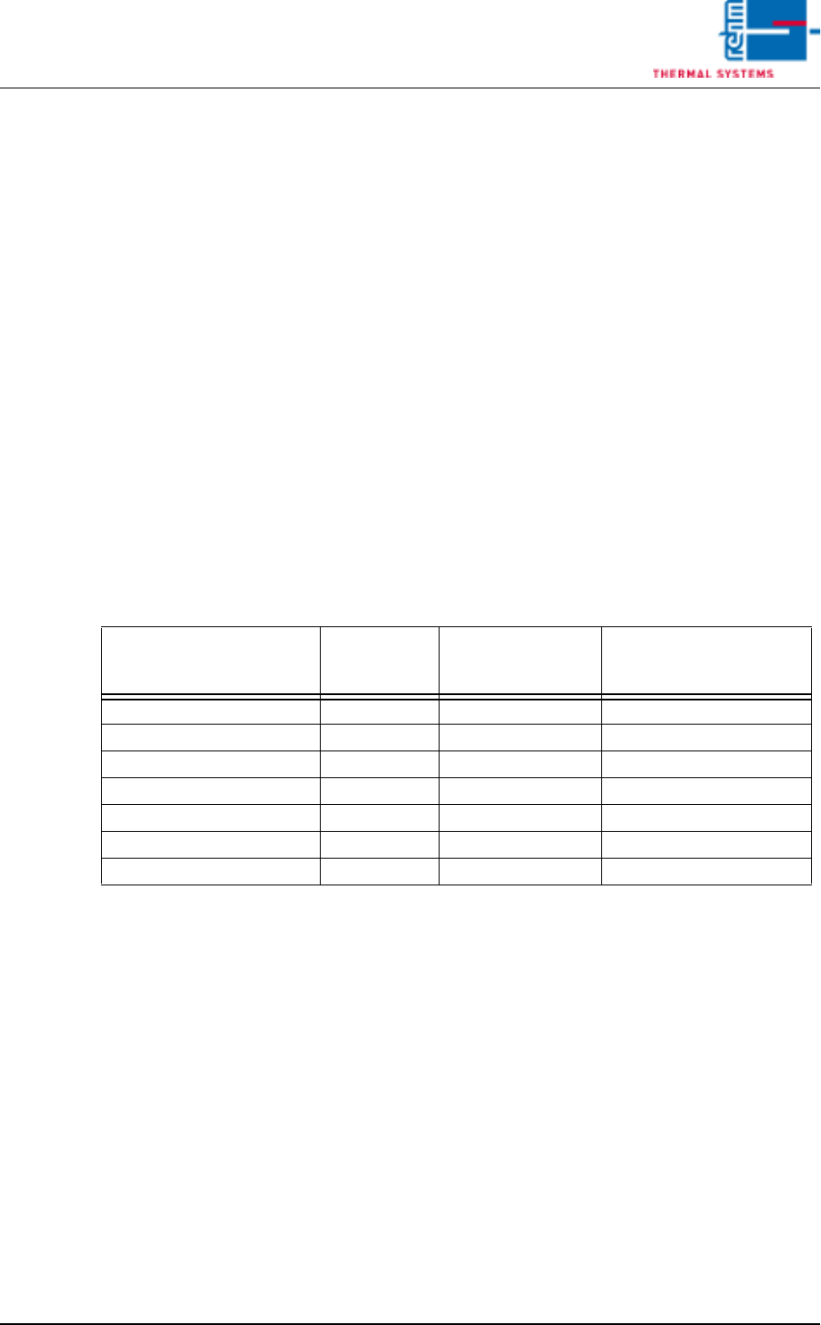
Function
Parameter
„Application“
Zone is criterion for
activation of the
function
Heating deactivated with
active function
Quick cooling down (SSP) 0 No No
Quick cooling down (SSP) 1 Yes No
Quick Exhaust 0 Yes No
Quick Exhaust 10 Yes Yes
Quick Exhaust 20 No Yes
Quick Exhaust 30 No No

Vision XP+ VAC Page 69
3 Setup Instructions
3.2 Temperature Channels
Operating Instructions
Version 1.5
If the cooling is located in another zone the control channel has to be en-
tered from the list (see page40).
Example 1
An system has cooling in zone 4 bottom instead of standard „cooling last
pre-heating zone“.
CoolPre_1: 13
CoolPre_2: 0
CoolPre_3: 0
Example 2
An system has cooling in zone 4 bottom instead of standard „cooling last
pre-heating zone“ and cooling in zone 1 bottom instead of cooling zone1
top.
CoolPre_1: 13
CoolPre_2: 10
CoolPre_3: 0