ServiceInstruction_Vision XP.pdf - 第82页
Page 78 Vision XP+ V AC 3 Setup Instructions 3.3 Conveyor Operating Instructions V ersion 1.5 D) Analog V alue The analog v alue which is curren tly being acquired fro m the rotary encoder is displ ayed here. E) Analog V…
Vision XP+ VAC Page 77
3 Setup Instructions
3.3 Conveyor
Operating Instructions
Version 1.5
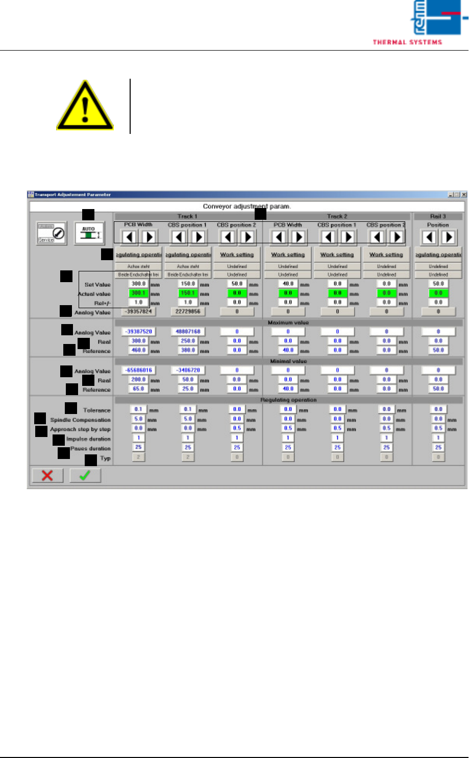
3.3.2 Conveyor Adjustment
Fig. 3-7 Conveyor Adjustment – Parameters
A) Conveyor adjustment can be operated either automatically or manually.
For further details refer to Main Window, in the chapter entitled “Software”
in the Operating Instructions.
B) Setpoints can be entered here, actual values are displayed and conveyor
tolerances can be entered. Beyond this, the status displays for the
conveyor units (axis) and error messages which have been triggered by
a PCB or the center support can be viewed. For further details refer to
Conveyor Values in the chapter entitled “Software” in the Operating
Instructions.
C) Setup Mode / Closed-Loop Control Mode
The conveyor side panels can be calibrated in the setup mode. Automatic
adjustment is deactivated for all conveyor side panels.
The conveyor side panels cannot be calibrated in the closed-loop control
mode. Automatic adjustment is activated. The default setting is closed-
loop control mode.
Note!
If a dual lane conveyor with asynchronous speed is utilized, the conveyor
speed for lane 2 must be checked separately using the same procedure.
A
C
B
B
D
E
F
G
H
I
J
K
L
M
N
O
P

Page 78 Vision XP+ VAC
3 Setup Instructions
3.3 Conveyor
Operating Instructions
Version 1.5
D) Analog Value
The analog value which is currently being acquired from the rotary
encoder is displayed here.
E) Analog Value, Maximum Values
Acquired analog value (D) which corresponds to the actual value (F).
F) Actual Maximum Values
Actual value which corresponds to the analog value (E).
G) Homing, Maximum Values
Entry of the maximum value for homing.
H) Analog Value, Minimum Values
Acquired analog value (D) which corresponds to the actual value (I).
I) Actual Minimum Values
Actual value which corresponds to the analog value (H).
J) Homing, Minimum Values
Entry of the minimum value for homing.
K) Tolerance
Control tolerance for automatic conveyor adjustment. The default
setting is 0.1.
L) Spindle Compensation
Spindle compensation for automatic conveyor adjustment. Spindle
compensation assures that the conveyor side panel is always
approached from the same side during automatic conveyor adjustment.
Mechanical tolerances and overrunning are compensated for in this way.
A value of greater than 0 always results in approach from the outside. A
value of less than 0 always results in approach from the inside. The
magnitude of the value determines to what extent the setpoint will be
overshot.
The default setting is 0.0.
M) Incremental Approach
Incremental approach allows for pulse controlled conveyor adjustment
just before the setpoint is reached. The default setting is 0.0.
N) Pulse Duration
The duration of the pulse for incremental approach is specified here. The
default setting is 1.
O) Pause Duration
The duration of the pause for incremental approach. The default setting
is 25.
P) Type
The type of conveyor side panel.
0 = no side panel
1 = side panel with manual conveyor adjustment
2 = side panel with automatic conveyor adjustment
Proceeding calibration
of PCB-width
Transport system has to be parallel for calibration!
1. Open the mask „Set-up“ in menu „Service“ and check if the transport is
released.
2. Switch the Automatic Width Adjustment to manual in the main mask.

Vision XP+ VAC Page 79
3 Setup Instructions
3.3 Conveyor
Operating Instructions
Version 1.5
3. Open the mask „Transport Adjustment Parameter“ in menu „Service“.
4. Switch the PCB-width from normal operation to set operation.
5. Insert the delivered set metal sheet to 300mm. The clearance between
transport and set metal sheet cannot be more than 1mm.
6. Enter the current analogue value in the „Analog Value Maximum Value“.
7. Set the real value to 300mm.
8. Then insert the set metal sheet to 200mm and enter this analog value at
„Analog Values Minimum Values“.
9. Set the real value to 200mm.
10. Switch over the software switch from set operation to normal operation
again.
11. Save the machine parameters in menu „Data“.
Proceeding: CBS-posi-
tion
Adjust the PCB-width to 300mm, insert the set metal sheet and mark two
fixed points.
100mm minimum value and
200mm maximum value.
Move to the maximum value and enter the analogue value as described
above for PCB-width.
Proceed in a similar manner with the minimum value and save the machine
parameters.