ServiceInstruction_Vision XP.pdf - 第68页
Page 64 Vision XP+ V AC 3 Setup Instructions 3.1 Adjustment Operating Instructions V ersion 1.5 3.1 Adjustme nt Fig. 3-2 Service Settings System-specific s ettings are specif ied in this window . A) Auto-Start-Sw itch Th…
Vision XP+ VAC Page 63
3 Setup Instructions
Operating Instructions
Version 1.5
3 Setup Instructions
This chapter concerns itself with all important system setup procedures.
These procedures must be executed when new components are installed,
or in the event that probe, sensor or transducer deviations are detected
during inspection.
The individual functions which require calibration or adjustment can be
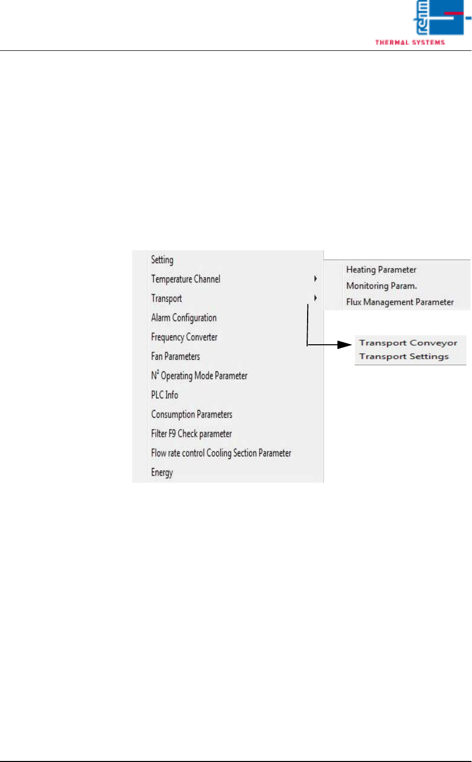
selected from the Service menu in the user interface.
Fewer functions may be included depending upon which system is used.
Fig. 3-1 The Service Menu
The Service menu can only be accessed by users with appropriate
password authority. When unauthorized users are logged on, the menu
appears light gray and is disabled.
Page 64 Vision XP+ VAC
3 Setup Instructions
3.1 Adjustment
Operating Instructions
Version 1.5
3.1 Adjustment
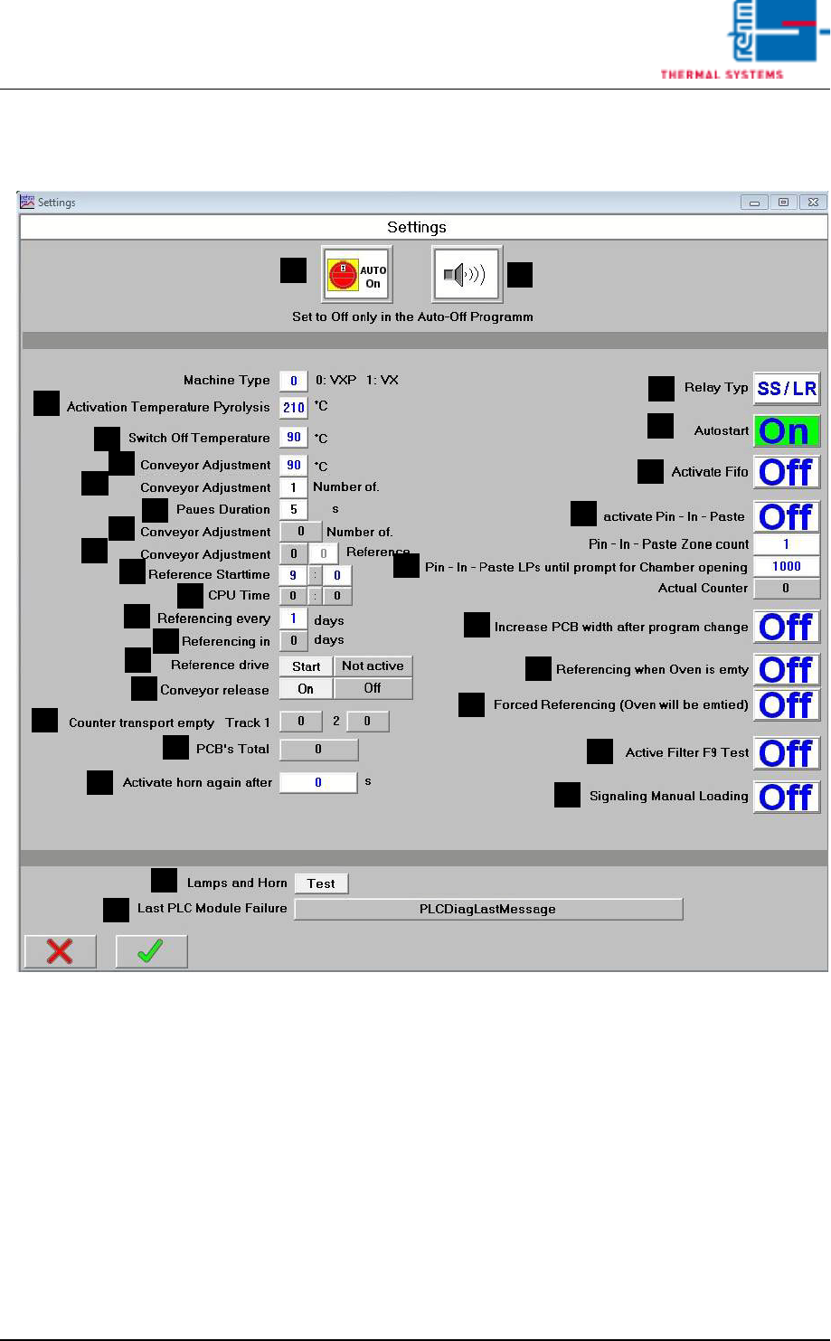
Fig. 3-2 Service Settings
System-specific settings are specified in this window.
A) Auto-Start-Switch
The drive unit, the heat, and compressed air can be turned on (auto-on)
of off (auto-off) simultaneously with this switch. the switch setting ist
stored to program memory.
B) Horn Switch
the horn sounds to indicate alarm messages which this switch is turned
on. If on the other hand, this switch is turned off, alarm messages appear
at the display only. The horn does not sound.
C) Temperature for pyrolysis activation
Only when a higher set value is preset in at least 2 peak-zones, the py-
rolysis is activated.
F
E
B
A
C
D
G
H
M
K
J
I
L
N
R
Q
P
O
S
T
U
V
W
X
Y
Z
AA
AB
AC
AD

Vision XP+ VAC Page 65
3 Setup Instructions
3.1 Adjustment
Operating Instructions
Version 1.5
D) Relay Type
Enables current monitoring for the entire conveyor adjustment system.
E) Auto On/Off
Automatic operation using the timetable (schedule), auto on/off software
button active or inactive.
F) Switch off temperature
This entry determines as of which temperature (for all active temperature
elements within the system) the shutdown routine is ended.
G) Conveyor Adjustment, °C
If actual temperature is less than the temperature selected here, neither
automatic nor manual conveyor adjustment can be activated.
H) Conveyor Adjustment, Number of Cycles
Number of adjusting cycles after loading a program (homing).
0 = homing deactivated.
1 = execute homing once a day (default setting)
2 to 254 = number of adjusting cycle for test purposes
255 = unlimited number of adjusting cycle for test purposes
I) Pause Duration
Pause in seconds before setpoints are activated during homing.
J) Conveyor Adjustment, Number of Cycles
Number of completed adjusting cycles
K) Conveyor Adjustment, Homing
Display and entry option for current homing progress. Homing can be
aborted by activating the emergency-stop button.
L) Reference Start time
Here the time is indicated when the reference run starts.
M) CPU Time
The current CPU time is indicated. By clicking the buttons in the margin
it can be updated.
N) Input field: reference run all n days
You can enter here if the reference run is daily (value), every other day
(value 2) or every three days (value 3).
O) Display field: reference run in n days
It is displayed here, in how many days there will be the next reference
run.
P) Reference Status
Over the button START the reference run can be started manually.
Reference Status:
-yellow: reference run will be carried out with the next program change.
-green: reference run will be carried out by activating the button refer-
ence.
Note!
As of now a reference run will be preset every 3 days at Rehm factory as a
standard. This is recommended by Rehm Thermal Systems.