ServiceInstruction_Vision XP.pdf - 第31页
Vision XP+ V AC Page 27 2 Maintenance 2.7 Cooling T ract Operating Instructions V ersion 1.5 2.7 Coolin g T ract 2.7.1 Cleaning the Cooling zone (passive area) Fig. 2-3 1 Cove r for Suct ion Cham ber Fig. 2-3 2 Sheet Met…
Page 26 Vision XP+ VAC
2 Maintenance
2.6 EC – Check gas blower
Operating Instructions
Version 1.5
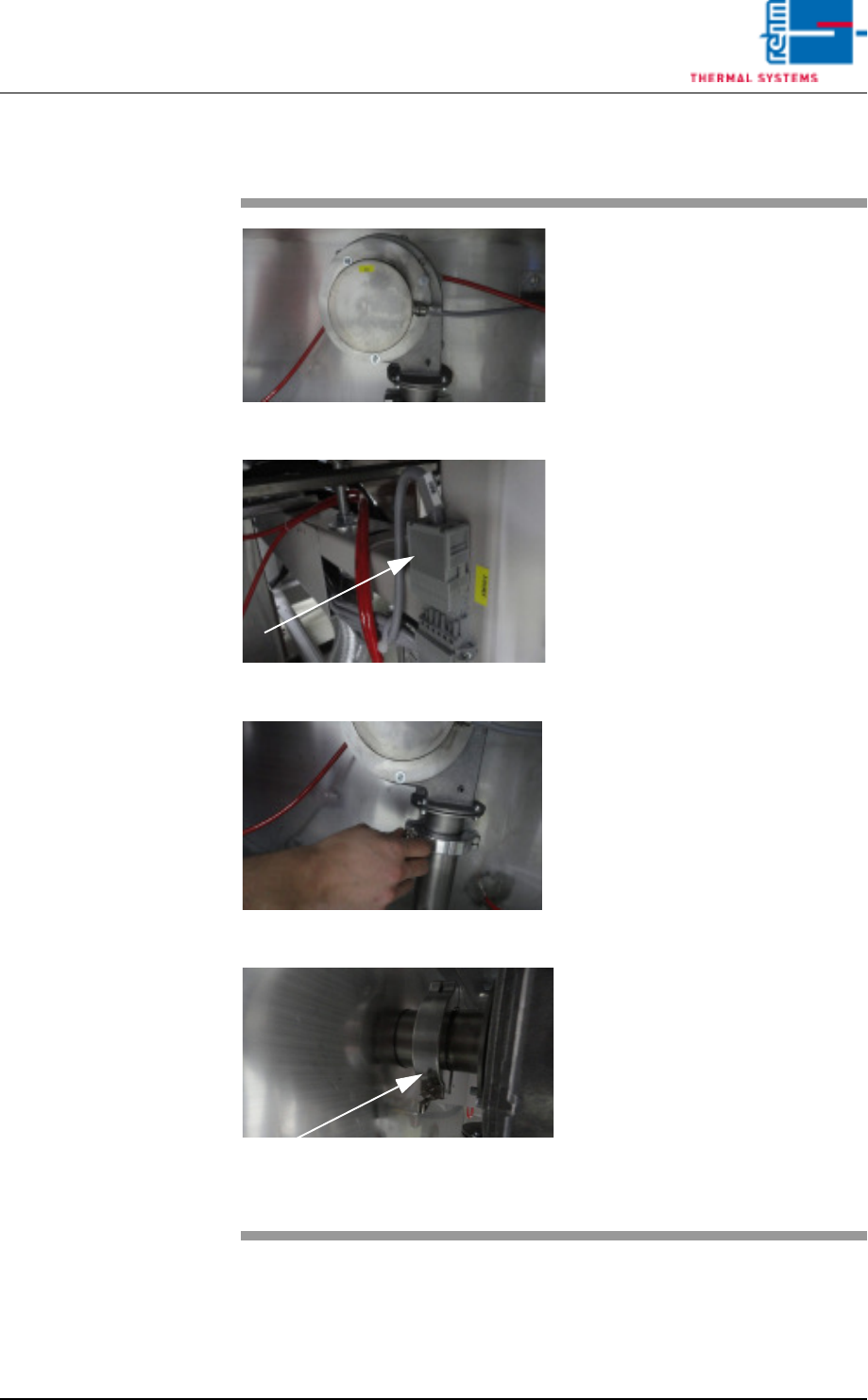
2.6.1 Uninstalling the EC gas blower
Fig. 2-27 Gas blower
Fig. 2-28 Gas blower 1
Fig. 2-29 Gas blower 2
Fig. 2-30 Gas blower 3
The EC gas blower is located at the
front of the machine, below the cool-
ing zone
Consumables, tools:
• Screwdriver
• Cleaning rags
Procedure:
1. Unplug the indicated plug to
isolate the gas blower from
mains.
2. Then open the front circlip on
the wing screw to loosen the
blower.
3. Also loosen the rear circlip on
the wing screw. The blower may
now be removed completely.
4. Now remove any residues from
the blow-out flange and fan
wheel and clean the blower with
a cleaning rag.
5. Finally, reassemble the blower
in reverse order and connect to
mains.
Vision XP+ VAC Page 27
2 Maintenance
2.7 Cooling Tract
Operating Instructions
Version 1.5
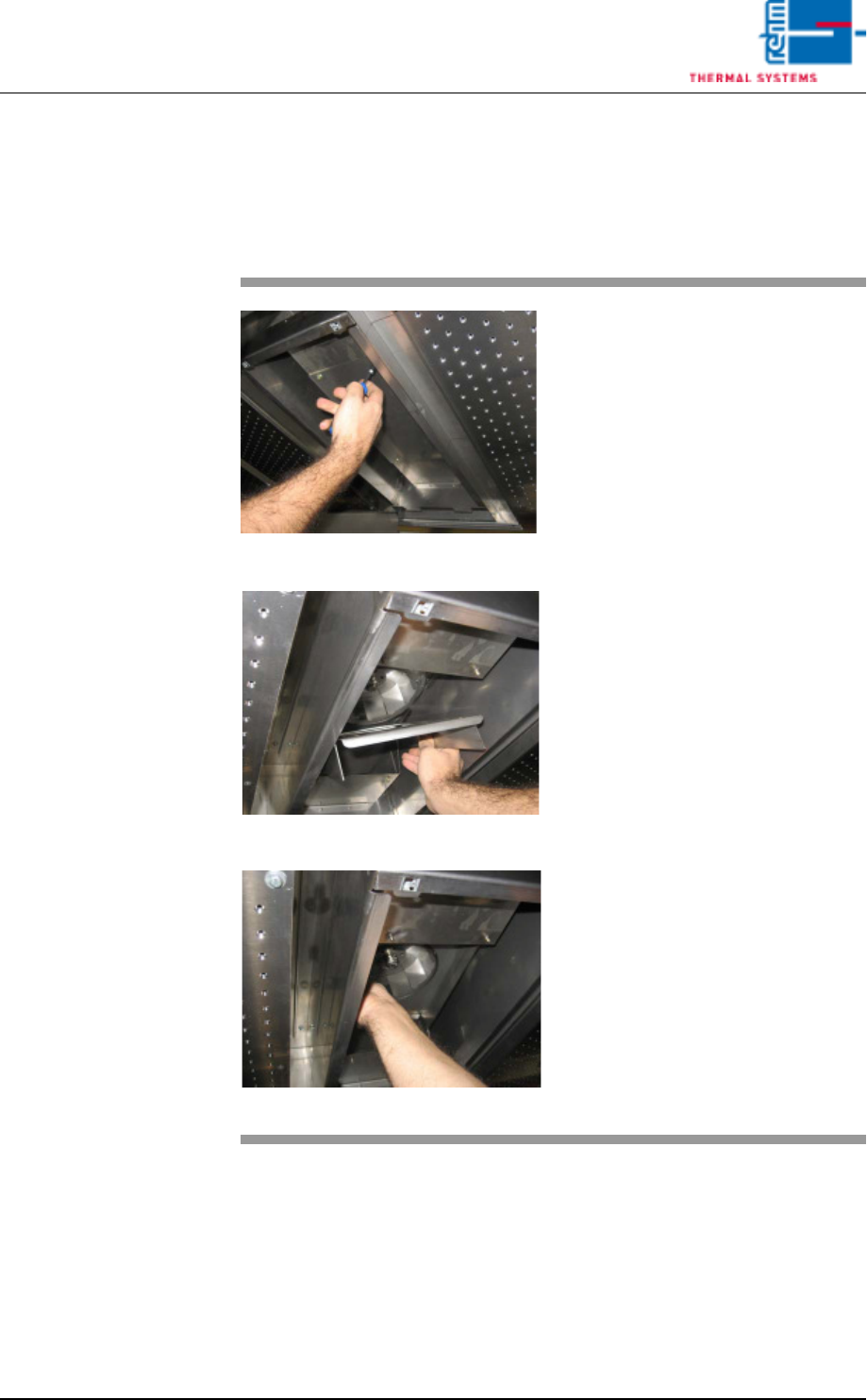
2.7 Cooling Tract
2.7.1 Cleaning the Cooling zone (passive area)
Fig. 2-31 Cover for Suction Chamber
Fig. 2-32 Sheet Metal Cover on Impeller
Fig. 2-33 Fan Impeller
The cooling zone can be dismantled
as described below. The individual
parts (e.g. nozzle field etc.) are
cleaned in a rinsing bath, or with
oven cleaner and rags.
Consumable materials, tools:
• Oven cleaner CF 1
• Rags
• Or rinsing bath
Procedure:
1. Loosen the screws on the noz-
zle sheet and lift it out.
2. Unscrew suction chamber cov-
er (see Fig. 2-31).
3. Remove the sheet metal cover
from the impeller (see Fig. 2-
32).
4. The fan impeller is now ex-
posed and can be inspected,
and cleaned with oven cleaner
and rags (see Fig. 2-33).
Page 28 Vision XP+ VAC
2 Maintenance
2.7 Cooling Tract
Operating Instructions
Version 1.5
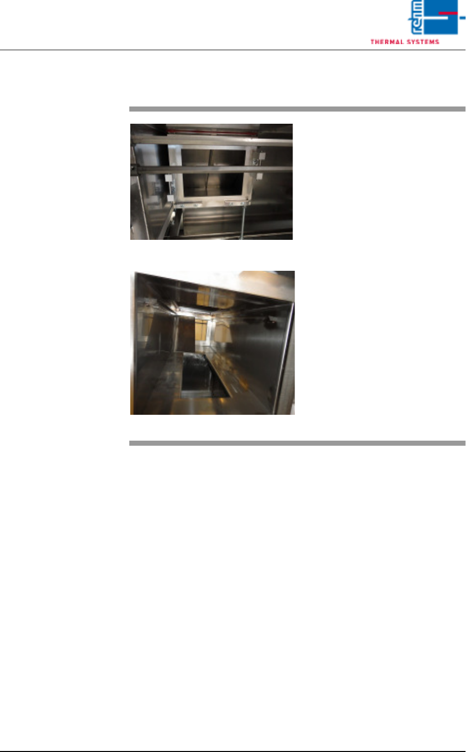
2.7.2 Additional cleaning chute VXP+
Fig. 2-34 Additional cleaning chute
Fig. 2-35 Additional cleaning chute 1
Consumables:
• Oven cleaner
• Cleaning rags
• Cleaning bath
An additional cleaning chute for the
cooling section is fitted at the front of
the plant.
This chute simplifies cleaning of the
cooling chute; the partitioning plates
may be individually removed and
placed in a suitable cleaning bath.
The cooling chute may now be
cleaned on both sides.
Thereafter reassemble everything
in reverse order.