ServiceInstruction_Vision XP.pdf - 第128页
Page 124 Vision XP+ V AC 3 Setup Instructions 3.22 Default V alues Operating Instructions V ersion 1.5 3.22.2 Alarm Configuration Default V alues Alarm Response T ype W arning Time Alarm T ime Emergency-St op 17 0 0 Phas…
Vision XP+ VAC Page 123
3 Setup Instructions
3.22 Default Values
Operating Instructions
Version 1.5
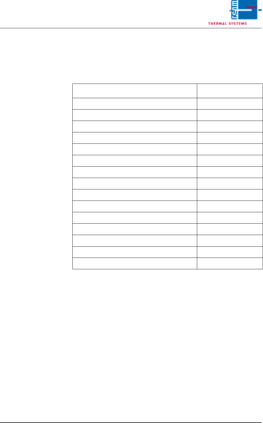
3.22 Default Values
3.22.1 Adjustment Default Values
Tab. 3-5 Adjustment Default Values
Type
Value
Activation Temperature Pyrolysis 210°C
Switch off temperature 90°C
Conveyor adjustment 90°C
Pause duration 5 s
Conveyor adjustment, Number of cycles 1
Referencing every 3 Days
Relay Typ SS/CR
Autostart On
Activate Fifo Off
Activate Pin - In - Paste Off
Increase PCB width after program change Off
Filter F9 Check while Referencing Off
Signaling Manual Loading Off
Cycle medium injection 00:30 mm:ss
Impulse medium injection 20 x 0,1 s
Page 124 Vision XP+ VAC
3 Setup Instructions
3.22 Default Values
Operating Instructions
Version 1.5
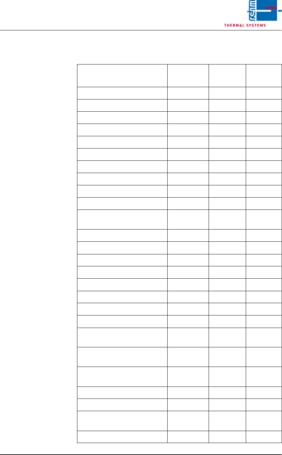
3.22.2 Alarm Configuration Default Values
Alarm
Response
Type
Warning
Time Alarm Time
Emergency-Stop 17 0 0
Phase Monitoring 16 0 0
Motor Protection 16 0 0
Frequency Converter 16 20 10
Frequency Cooling Tract 5 20 10
Cooling section 5 0 0
Fan Monitoring 16 20 10
Exhaust 4 10 0
Process Chamber Open 5 0 0
Heating Elements Monitoring 4 10 0
Excess temperature protection
was released
16 0 0
Drive Motor 1 0 0
Condensate Trap 3 0 0
Condensate trap error 3 0 0
Power supply error 16 0 0
Cooling tract circulation 4 10 0
Standstill Monitoring 17 10 30
Speed Tolerance Violation 3 10 0
Upper Temperature Limit Value 16 5 10
Maximum Temperature Toler-
ance
3 0 120
Minimum Temperature Toler-
ance
3 0 120
Heating element power control-
ler error
4 10 0
PCB Feed Monitoring, Lane 1 3 10 0
PCB Transfer jam, Lane 1 16 0 30
Outlet Interface, Lane 1 (with
Siemens-Interface only)
1 0 0
Error Circuit, Lane 1 1 0 0
Vision XP+ VAC Page 125
3 Setup Instructions
3.22 Default Values
Operating Instructions
Version 1.5
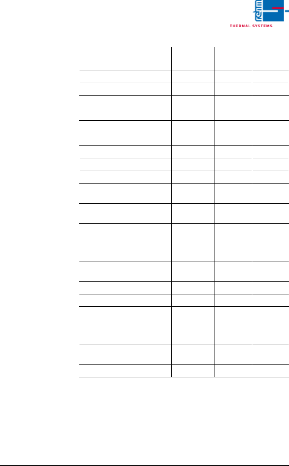
Tab. 3-6 Alarm Configuration (default values)
Cooling water 16 10 10
Too little water 24 10 720
Water Leak 16 0 0
Cooling System 3 10 0
N2 consumption OK 1 20 0
N2/O2 Pressure to low 4 30 0
Residual Oxygen Meter 4 10 0
O2 Tolerance Violation 3 5 0
Condensation bottles are full 24 10 720
Flow monitoring residue man-
agement
4 180 180
Filling level Chain Lubricator too
low.
24 10 720
SPS Field Modules 16 0 0
SPS Communication 1 2 0
Transport adjustment OK 3 0 0
Supervision of PCB-dropping
was released
16 1 0
Conveyor Adjustment Current 14 0 0
Conveyor Drive Current 3 10 0
MES Release 0 0 0
PCB Feed Monitoring, Lane 2 3 10 0
PCB Transfer, Lane 2 16 0 30
Outlet Interface, Lane 2 (with
Siemens-Interface only)
1 0 0
Error Circuit, Lane 2 1 0 0
Alarm
Response
Type
Warning
Time Alarm Time