ServiceInstruction_Vision XP.pdf - 第93页
Vision XP+ V AC Page 89 3 Setup Instructions 3.5 Frequency Converter Operating Instructions V ersion 1.5 T ab. 3-3 Paramet er Mitsu bishi FR-D 700 For any other v alues or an y fu rther functions please refer to th e enc…
Page 88 Vision XP+ VAC
3 Setup Instructions
3.5 Frequency Converter
Operating Instructions
Version 1.5
3.5.2 Typ Mitsubishi FR-D 700
Setting system
parameters
In connection with a Siemens control
Note!
If a signal is upcoming at the clamp „STR or „STF“ the parameter P4 can be
changed all the same.
1. Start with point 2 if the frequency converters 24V are not activated. As
long as the system conveyor is running, a signal is on the „STR or STF“
clamp and the converters are locked for any entry. To change the set-
tings, the „STR“ or „STF“ clamp needs to be disconnected. Stop the fre-
quency converter with the stop button.
2. First set the operating mode to 0, as otherwise the other parameters
cannot be checked or changed.
Press button Mode, on the display any type of parameter is indicated.
Select the parameter P79 with the Digital Dial.
Press button Set and set the value to 0 with the Digital Dial. Press button
Set for confirmation.
Return to the starting position with the button Mode.
3. For changing the parameter settings press the PU/EXT key until the
LED below PU lights up. (Switching over to the PU operation mode is
only possible if the inverter is at a stop).
4. When the Mode key is pressed, P 0 is shown on the display.
5. Press the Set key to read the currently set value for the selected param-
eter.
6. The newly selected value is then saved to memory by activating the Set
key. The display returns once again to the parameters window.
7. The newly selected value is then saved to memory by activating the Set
key. The display returns once again to the parameters window.
8. Steps 5 through 8 must then be repeated if additional parameters need
to be changed.
9. The frequency converter must be returned to the EXT operating mode
by pressing the PU/EXT key in order to exit the parameter setting func-
tion.
10. Operating parameter 79 must once again be set to the value specified
in the table as described in point 2. Re-clamp the triggering STR at the
frequency converter.
The list below shows all parameters which have been set as standard val-
ues.
Attention!
The heaters may not exceed a temperature of 70° C, because the fans
might otherwise overheat.
Vision XP+ VAC Page 89
3 Setup Instructions
3.5 Frequency Converter
Operating Instructions
Version 1.5
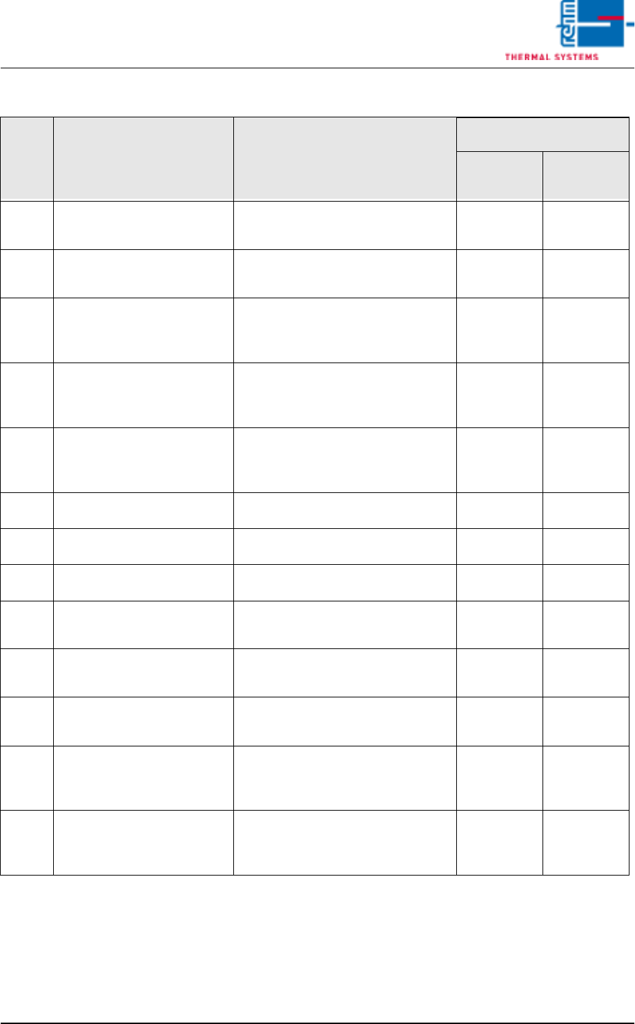
Tab. 3-3 Parameter Mitsubishi FR-D 700
For any other values or any further functions please refer to the enclosed In-
struction Manual of the inverter.
Para-
meter Function Description of the set parameters
Settings
Heating
Cooling
zone
1
Maximum output
frequency 0 to 120 Hz 60 60
2
Minimum output
frequency 0 to 120 Hz 30 20
4
1st multi-speed
selection - RH
0 to 120 Hz
(setpoint as in calibration
certificate)
Example
45
Example
45
5
2nd multi-speed
selection - RM
0 to 120 Hz
(setpoint as in calibration
certificate option)
Example
35
Example
35
6
3rd multi-speed
selection - RH
0 to 120 Hz
(setpoint as in calibration
certificate option)
Example
25
Example
25
7
Acceleration time 0 to 999 sec. 10 10
8
Deceleration time 0 to 999 sec. 20 20
19
Maximum output voltage 0 to 500 (800) V 400 400
125
Frequency at 5V-10V
input voltage
0 to 120 Hz
(frequency setting via software) 100 100
161
Operation selection of
setting Digital Dial
0: frequency setting mode
1: potentiometer mode 1 1
192
A,B,C terminal function
selection
For setting options refer to operat-
ing instructions of inverter 0 0
73
Specification of setpoint
input data
0: 0 to 10 V DC
1: 0 to 5V DC
(frequency setting via software) 0 0
79
Operation mode
selection
2: Setpoint assignment via PC
3: Setpoint assignment 24V fixed
voltage 3 2

Page 90 Vision XP+ VAC
3 Setup Instructions
3.5 Frequency Converter
Operating Instructions
Version 1.5
Note!
Specific adjustments should only be made by the service engineers of
Rehm Thermal Systems GmbH.