ServiceInstruction_Vision XP.pdf - 第117页
Vision XP+ V AC Page 1 13 3 Setup Instructions 3.16 Adjustment, Inspection Operating Instructions V ersion 1.5 3.16.3 Checking Center Support Position This procedure should only be executed after checking conveyor width …
Page 112 Vision XP+ VAC
3 Setup Instructions
3.16 Adjustment, Inspection
Operating Instructions
Version 1.5
3.16.2 Adjusting the Conveyor Side Panels
If, after inspecting the conveyor side panels, tolerance violations are
discovered which cannot be eliminated by means of calibration, the convey-
or side panels must be mechanically readjusted.
Procedure:
1. Set conveyor width to 200 mm.
2. Set the 200 x 300 mm sheet metal panel onto the conveyor at the inlet.
3. The gap between the conveyor and the panel should be no larger than
1 mm; otherwise width must once again be readjusted.
4. Push the sheet metal panel to the next station to which the conveyor
side panel to be adjusted is screwed (2, optionally 4).
5. Check the gap. If the gap is greater than 2 mm, the conveyor side panel
must be adjusted.
6. Open the door underneath the side panel.
11. Push the sheet metal panel to the next station and repeat the above
described procedure.
12. After all stations have been adjusted, push the sheet metal panel back
to the inlet. The gap may not exceed 2 mm over the entire length of the
conveyor, otherwise the procedure must be repeated.
Note!
The fixed side panel, or the third side panel if a dual-lane conveyor is used,
should not be changed.
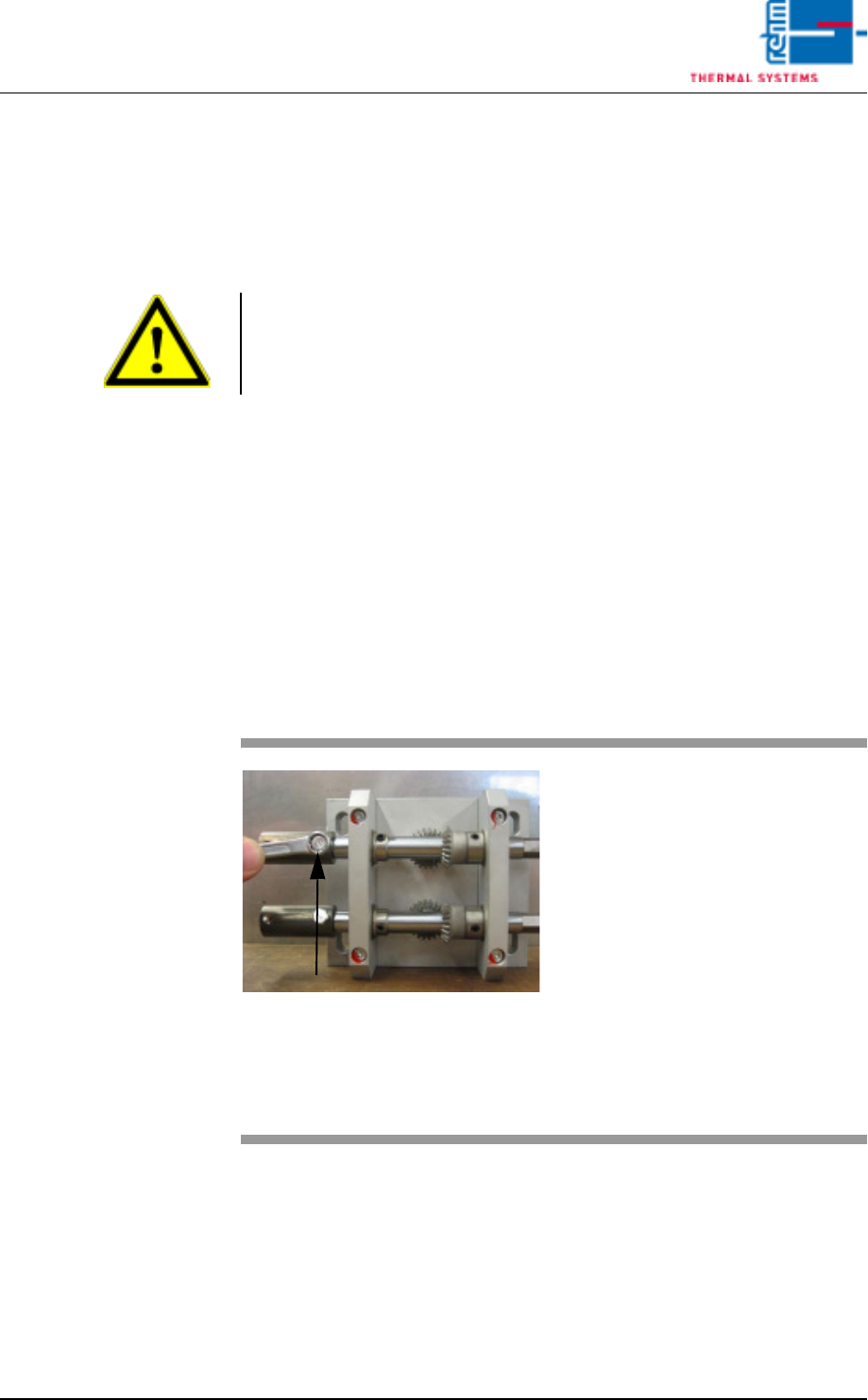
Fig. 3-23 Adjusting the Conveyor Side Panel
7. Remove the right and left hex
head screws from the drive at
the upper shaft.
Tip: If a sheet metal panel with a
width of 200 mm is used, the
mounting screws can be easily
accessed.
8. Push the coupling for the
hexagonal shaft away from the
drive unit.
9. Turn the drive manually until the
gap is less than 2 mm.
10. Push the coupling back into
place and tighten the screws.

Vision XP+ VAC Page 113
3 Setup Instructions
3.16 Adjustment, Inspection
Operating Instructions
Version 1.5
3.16.3 Checking Center Support Position
This procedure should only be executed after checking conveyor width and
calibrating if necessary.
Procedure:
1. Discharge all PCBs from the system. The conveyor must be completely
empty of PCBs.
2. Set conveyor width to 200 mm in the main window.
3. Open the process chamber with the software button.
4. Set center support positioning to 100 mm in the main window, or in the
Conveyor Adjustment window. Wait until the center support has
reached the selected position.
5. Set the 200 x 300 mm sheet metal panel onto the conveyor and push it
slowly through the system. Continuously monitor clearance between the
center support and the panel at the stations, and make sure that the cen-
ter support is precisely aligned to the oblong holes in the panel.
6. If positioning deviates over the entire length of the conveyor, the center
support must be calibrated. If the position of the center support relative
to the middle of the plate varies greatly over the length of the conveyor,
the individual stations must be mechanically adjusted (see chapter
3.2.10).
7. Remove the sheet metal panel from the outlet.
8. If center support position is OK, work can be continued.
Note!
If the system is equipped with a dual-lane conveyor, the same procedure is
used for both lanes.
Page 114 Vision XP+ VAC
3 Setup Instructions
3.16 Adjustment, Inspection
Operating Instructions
Version 1.5
3.16.4 Adjusting the Center Support
Center support position must be adjusted:
• If the distance from the center support to the fixed side panel is not always
100 mm
• If the center support can no longer be set correctly by means of calibration
• If visual inspection reveals that the center support no longer runs in a
straight line
Procedure:
1. Set conveyor width to 200 mm.
2. Set the 200 x 300 mm sheet metal panel onto the conveyor at the inlet.
3. The center support should be at the middle of the sheet metal panel. If
this is not the case, it must be recalibrated.
4. Push the sheet metal panel to the next station to which the center
support is screwed.
5. Check positioning of the center support to the sheet metal panel once
again. If the center support is more than 2 mm from the middle of the
panel, it must be adjusted.
6. Open the door underneath the side panel.
11. Push the sheet metal panel to the next station and repeat the above de-
scribed procedure.
12. After all stations have been adjusted, push the sheet metal panel back
to the inlet. The gap may not exceed 2 mm over the entire length of the
conveyor, otherwise the procedure must be repeated.
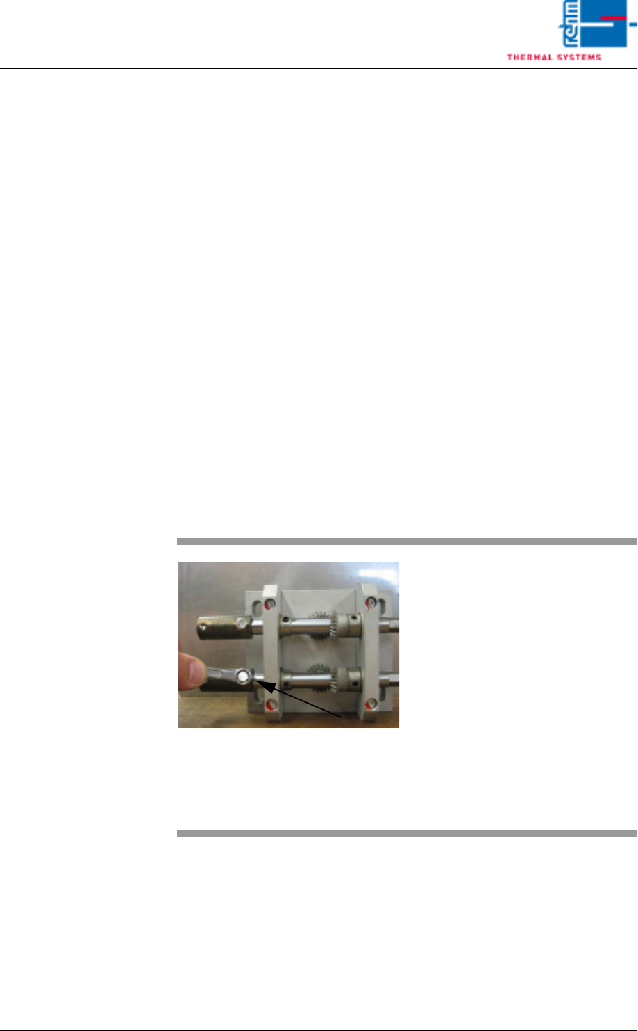
Fig. 3-24 Adjusting the Center Support
7. Remove the right and left hex
head screws from the drive at
the lower shaft.
Tip: If a sheet metal panel with a
width of 200 mm is used, the
mounting screws can be easily
accessed.
8. Push the coupling for the
hexagonal shaft away from the
drive unit.
9. Turn the drive manually until the
gap is less than 2 mm.
10. Push the coupling back into
place and tighten the screws.