ServiceInstruction_Vision XP.pdf - 第119页
Vision XP+ V AC Page 1 15 3 Setup Instructions 3.17 T e aching of Ultrasonic Sensor Inlet and Outlet Operating Instructions V ersion 1.5 3.17 T eachi ng of Ul trasonic Sensor Inl et and Out let In order the obtain the c …
Page 114 Vision XP+ VAC
3 Setup Instructions
3.16 Adjustment, Inspection
Operating Instructions
Version 1.5
3.16.4 Adjusting the Center Support
Center support position must be adjusted:
• If the distance from the center support to the fixed side panel is not always
100 mm
• If the center support can no longer be set correctly by means of calibration
• If visual inspection reveals that the center support no longer runs in a
straight line
Procedure:
1. Set conveyor width to 200 mm.
2. Set the 200 x 300 mm sheet metal panel onto the conveyor at the inlet.
3. The center support should be at the middle of the sheet metal panel. If
this is not the case, it must be recalibrated.
4. Push the sheet metal panel to the next station to which the center
support is screwed.
5. Check positioning of the center support to the sheet metal panel once
again. If the center support is more than 2 mm from the middle of the
panel, it must be adjusted.
6. Open the door underneath the side panel.
11. Push the sheet metal panel to the next station and repeat the above de-
scribed procedure.
12. After all stations have been adjusted, push the sheet metal panel back
to the inlet. The gap may not exceed 2 mm over the entire length of the
conveyor, otherwise the procedure must be repeated.
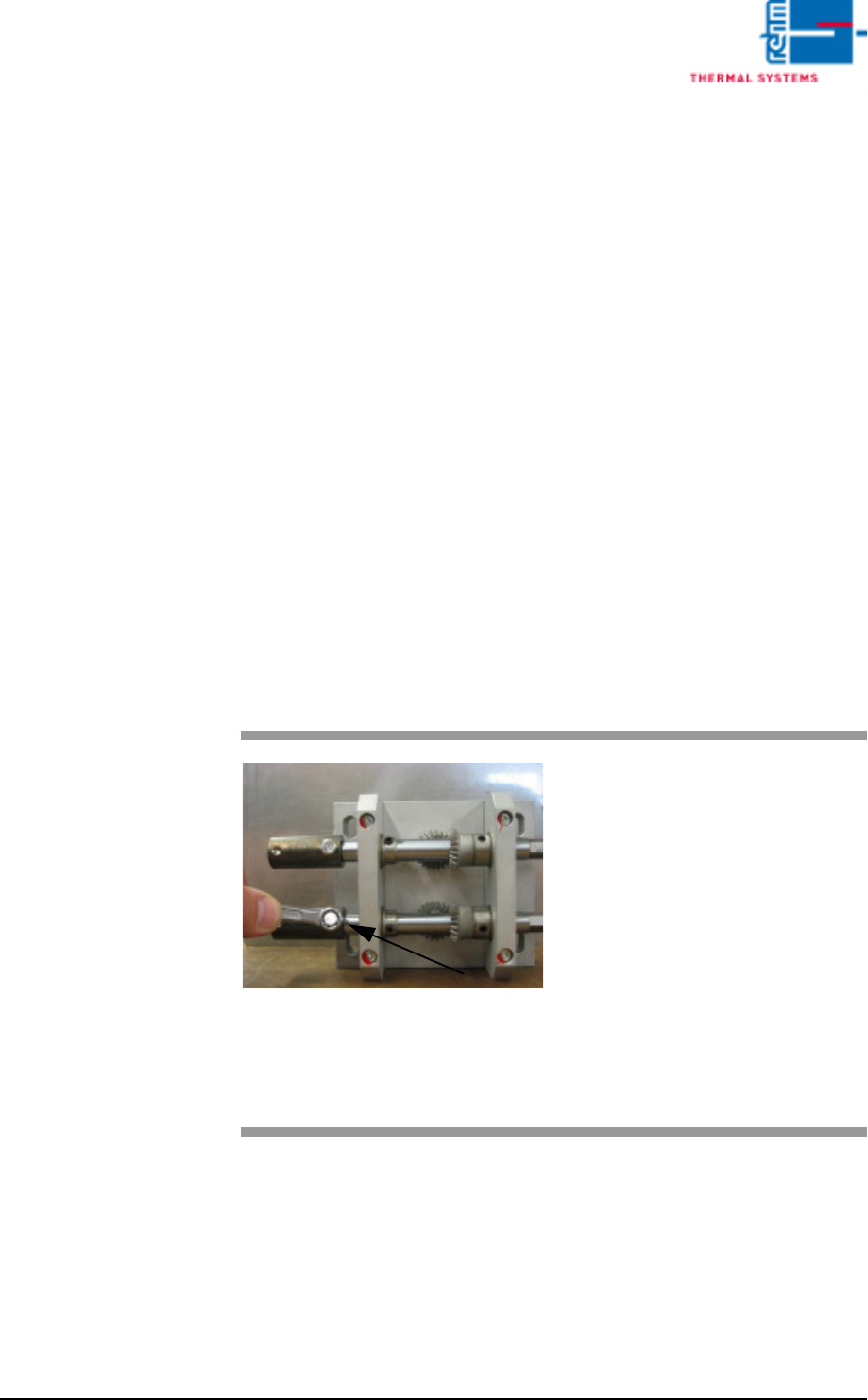
Fig. 3-24 Adjusting the Center Support
7. Remove the right and left hex
head screws from the drive at
the lower shaft.
Tip: If a sheet metal panel with a
width of 200 mm is used, the
mounting screws can be easily
accessed.
8. Push the coupling for the
hexagonal shaft away from the
drive unit.
9. Turn the drive manually until the
gap is less than 2 mm.
10. Push the coupling back into
place and tighten the screws.
Vision XP+ VAC Page 115
3 Setup Instructions
3.17 Teaching of Ultrasonic Sensor Inlet and Outlet
Operating Instructions
Version 1.5
3.17 Teaching of Ultrasonic Sensor Inlet and Outlet
In order the obtain the correct switching point of the ultrasonic sensor it has
tube calibrated by means of the teaching procedure. Example at the inlet.
Note!
If the system is equipped with a dual-lane conveyor, the same procedure is
used for both lanes.
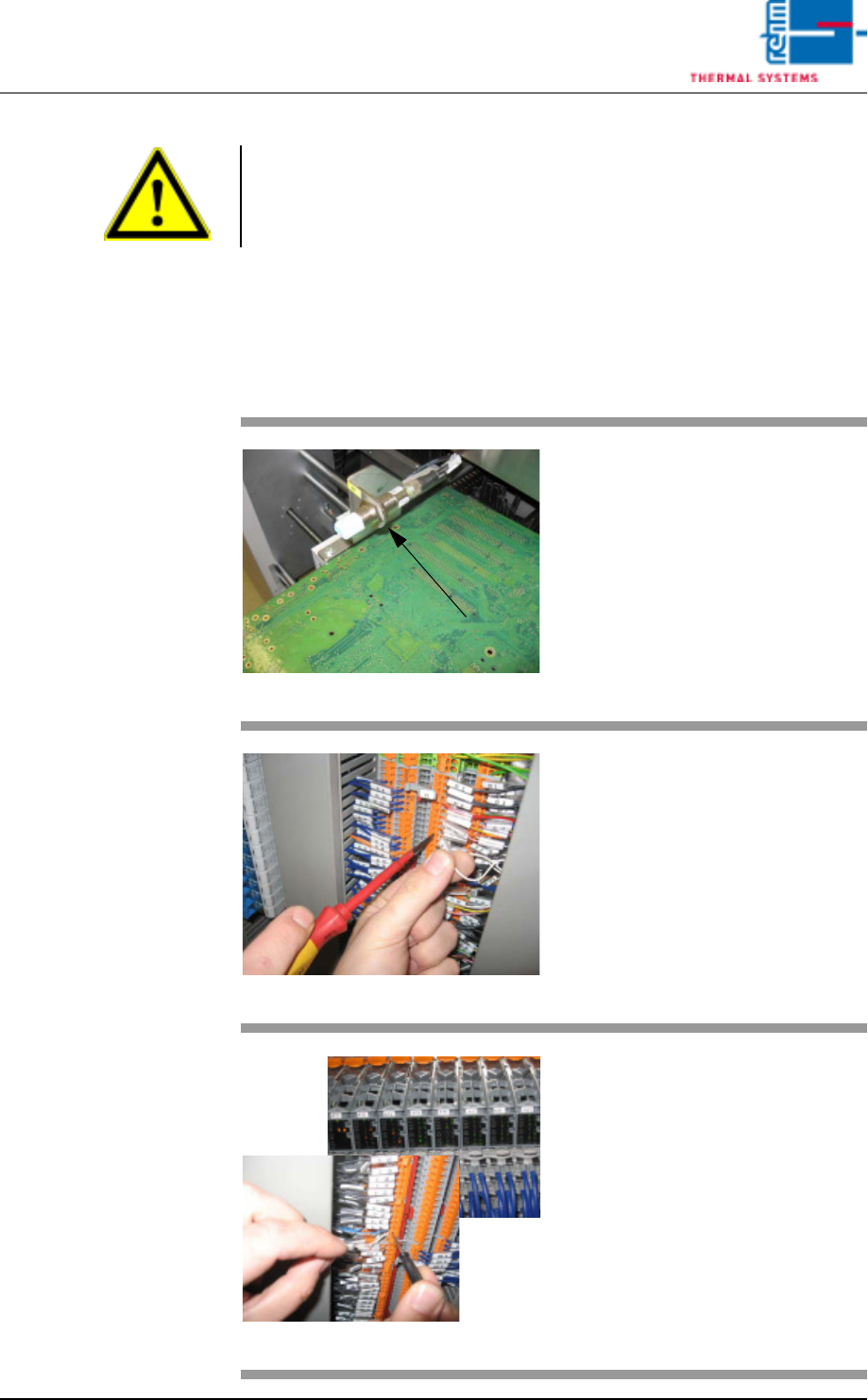
Fig. 3-25 Ultrasonic senor
Put one PCB over the conveyor
onto the conveyor rails sot that the
sensor is covered
Fig. 3-26 Terminal X1
Open the switch cabinet door
behind which the terminal block X1
is located (see the wiring diagram
white wire).
Fig. 3-27 X- terminal and SPS
Remove the white wire of the light
barrier (WB1) from the
open-circuited terminal.
Hold for >3 sec. onto the X-terminal.
Now, the ultrasonic sensor is
flashing twice.
When the ultrasonic sensor
(SPS- entry) doesn't flash any
more, clamp the white wire again
into the blank terminal.

Page 116 Vision XP+ VAC
3 Setup Instructions
3.17 Teaching of Ultrasonic Sensor Inlet and Outlet
Operating Instructions
Version 1.5
Note!
The sensor at the outlet ist taught with the same procedure. The sensor ist
connected on the X1 terminal board.