ServiceInstruction_Vision XP.pdf - 第84页
Page 80 Vision XP+ V AC 3 Setup Instructions 3.3 Conveyor Operating Instructions V ersion 1.5 3.3.3 Chain Lubricator Fig. 3-8 Chain Lubricato r Always when th e Chain Lu bricator is activated ( impulse duration valve), t…

Vision XP+ VAC Page 79
3 Setup Instructions
3.3 Conveyor
Operating Instructions
Version 1.5
3. Open the mask „Transport Adjustment Parameter“ in menu „Service“.
4. Switch the PCB-width from normal operation to set operation.
5. Insert the delivered set metal sheet to 300mm. The clearance between
transport and set metal sheet cannot be more than 1mm.
6. Enter the current analogue value in the „Analog Value Maximum Value“.
7. Set the real value to 300mm.
8. Then insert the set metal sheet to 200mm and enter this analog value at
„Analog Values Minimum Values“.
9. Set the real value to 200mm.
10. Switch over the software switch from set operation to normal operation
again.
11. Save the machine parameters in menu „Data“.
Proceeding: CBS-posi-
tion
Adjust the PCB-width to 300mm, insert the set metal sheet and mark two
fixed points.
100mm minimum value and
200mm maximum value.
Move to the maximum value and enter the analogue value as described
above for PCB-width.
Proceed in a similar manner with the minimum value and save the machine
parameters.
Page 80 Vision XP+ VAC
3 Setup Instructions
3.3 Conveyor
Operating Instructions
Version 1.5
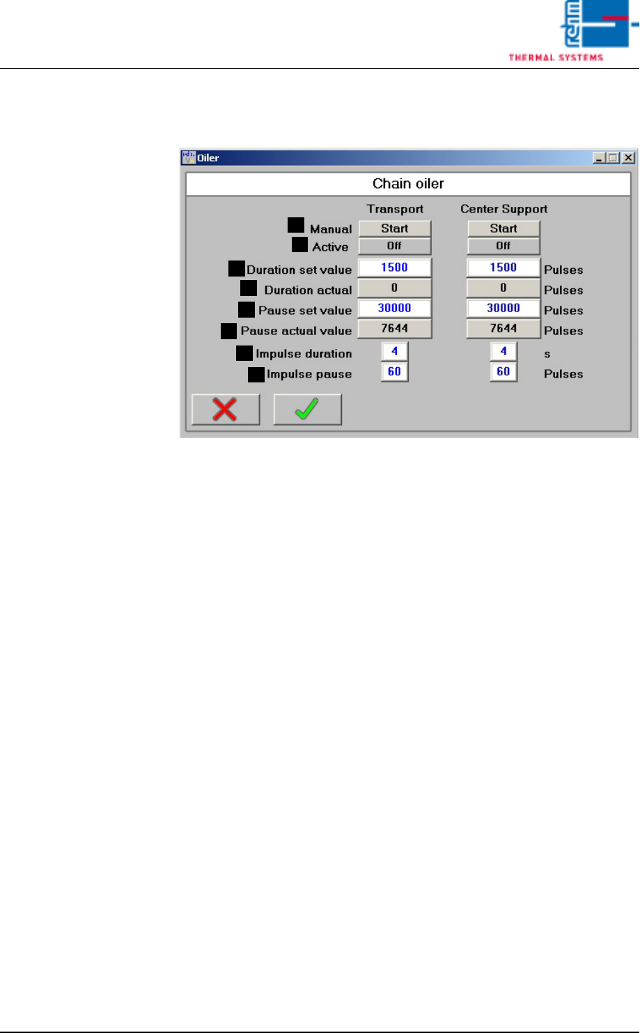
3.3.3 Chain Lubricator
Fig. 3-8 Chain Lubricator
Always when the Chain Lubricator is activated (impulse duration valve), the
pump pistons are moved once. A constant defined ejection volume is
ejected at the outlet.
If the electric solenoid is de-energized (impulse pause valve), the pump pis-
tons are put into the initial stae through spring force and suck chain oil for
the next ejection.
A) Start the Chain Lubricator manually
The Chain Lubricator is started independently of pause must value.
B) Indication Chain Lubricator active
C) Duration set value
Number of impulses from the conveyor chain for which the Chain Lubri-
cator is active after the pause.
D) Duration actual
Indication of the counted impulses so far.
E) Pause set value
Number of impulses from the conveyor chain for which the Chain Lubri-
cator is not active after the pause.
F) Pause actual value
Indication of the counted impulses so far.
G) Impulse duration valve (time)
Here it can be specified for which time the Chain Lubricator is controlled
with voltage. The default value is 4.
H) Impulse pause valve (pulses)
Here the break between the ejections of the Automatic Chain Lubrication
can be indicated. The entry is in impulses of the conveyor system. The
default value is 60.
G
F
H
B
A
C
D
E
Vision XP+ VAC Page 81
3 Setup Instructions
3.4 Alarm Configuration
Operating Instructions
Version 1.5
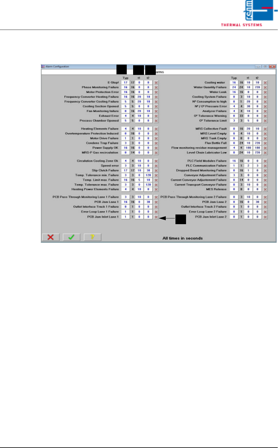
3.4 Alarm Configuration
Fig. 3-9 Alarm Configuration
A) Type
Default values are displayed here for the entry of alarm types. Deviations
are machine-specific.
B) t1 (warning time)
Warning time is the delay time which elapses from the point in time at
which an alarm event occurs until the alarm message appears at the
display. The setpoint is entered in seconds.
C) t2 (response time)
Delay time from the point in time at which the alarm message is displayed
(warning time t1) until the alarm is triggered (response time t2) can be
entered under alarm time. Time is entered in seconds.
D) Selection display for Kick Off relay function
If the system ist loaded and an alarm is released when the kick off relay
function ist activated, the system locks the inlet interface an transports
the remaining boards outward which are still in the heating chamber. Dur-
ing the elimination a signal is sent to the subsequent system. Through
this signal the subsequent system is informed which parts are moved out-
ward for exact checking. When all boards are outside of the system, the
inlet
interface is released again an the production run on as usual.
In the alarm mask you can select by which alarms the kick off relay
should release.
A
B
C
D