ServiceInstruction_Vision XP.pdf - 第49页
Vision XP+ V AC Page 45 2 Maintenance 2.10 W ater T ank - Checking and Refilling the W ater Fill-Level (Option) Operating Instructions V ersion 1.5 2.10 W ate r T ank - Checkin g and Ref illing th e W a ter Fill-Leve l (…
Page 44 Vision XP+ VAC
2 Maintenance
2.9 Cleaning the Exhaust Filters at the Inlet and the
Outlet
Operating Instructions
Version 1.5
2.9 Cleaning the Exhaust Filters at the Inlet and the Outlet
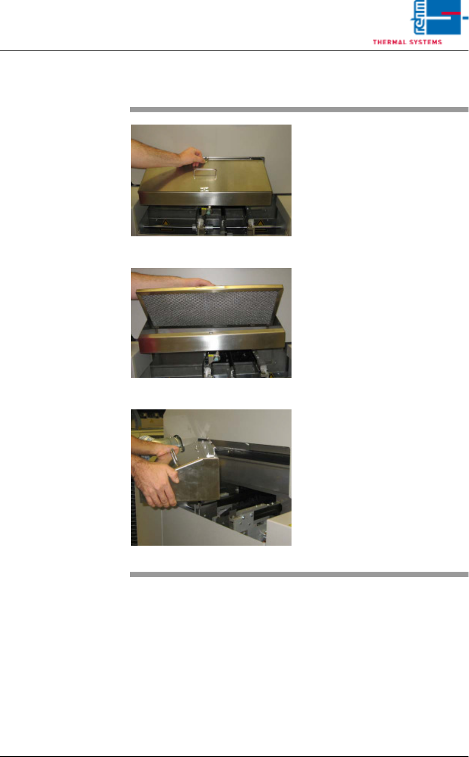
Fig. 2-64 Pulling Out the Filter Housing
Fig. 2-65 Lifting the Filter Out of the Housing
Fig. 2-66 Lifting the Filter Housing
Consumable materials, tools:
• Oven cleaner
• Rags
• Or rinsing bath
Procedure:
1. Pull out the filter housing along
with the metallic gauze filter.
2. Loosen the wing screws and lift
the filter out of the filter housing.
3. Set the metallic gauze filter into
a rinsing bath. If a rinsing bath is
not available, the filter can be
cleaned with oven cleaner and
rags.
4. Lift the filter housing and set it
into a rinsing bath as well, or
clean it with oven cleaner and
rags.
5. After cleaning the filter, set it
back into the filter housing and
reinstall it into the system
Vision XP+ VAC Page 45
2 Maintenance
2.10 Water Tank - Checking and Refilling the Water
Fill-Level (Option)
Operating Instructions
Version 1.5
2.10 Water Tank - Checking and Refilling the Water Fill-Level (Op-
tion)
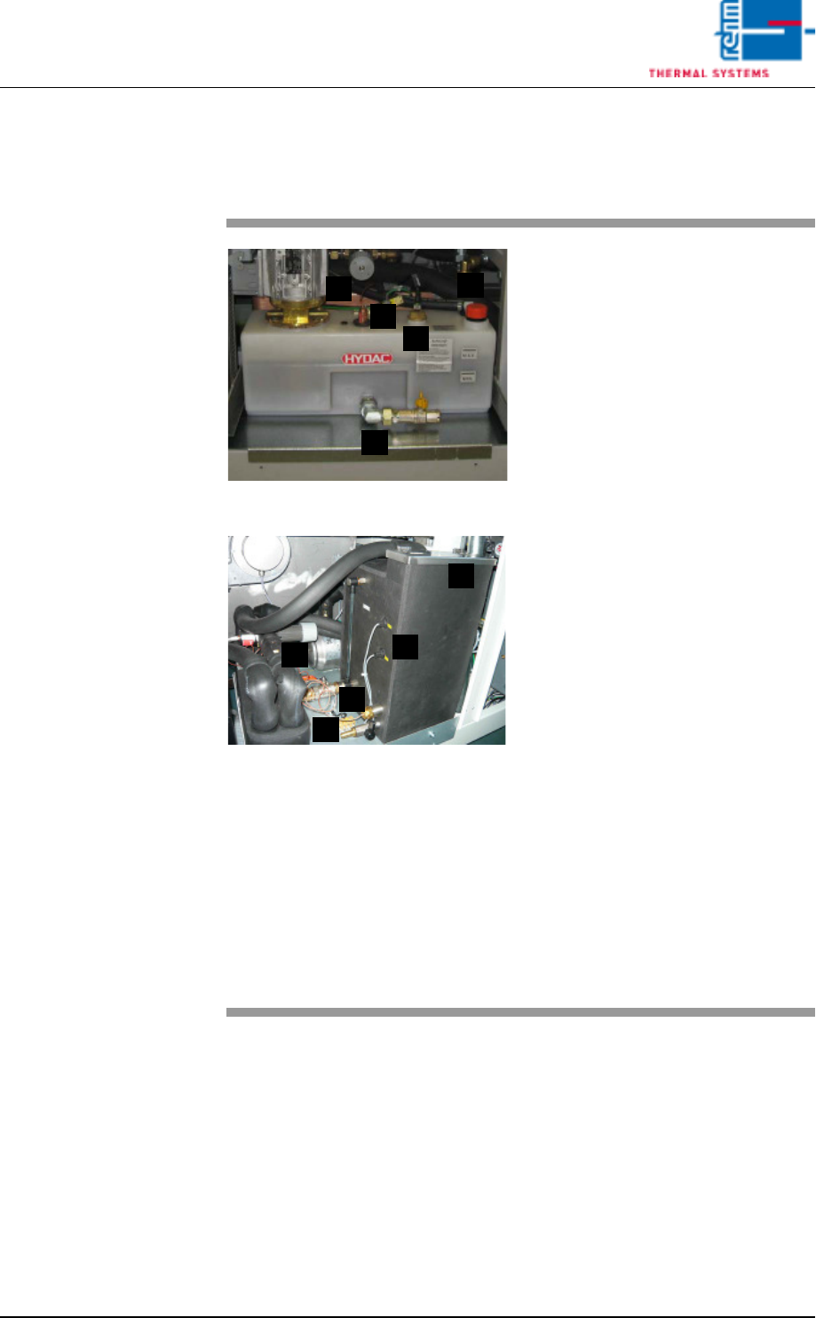
Fig. 2-67 Checking the Water Fill-Level
Fig. 2-68 Checking the Water Fill-Level, CN
The water tank is located behind the
second door from the right.
Consumable materials, tools:
• Water
• Antifreeze
Note!
Coolant is mixed using 1 part an-
tifreeze to 3 parts water.
• Watering can or similar container
Procedure:
1. The front of the water tank is
marked with the designations
MAX. and MIN.
2. When the fill-level drops to the
minimum mark, the tank must
be refilled with coolant to the
maximum mark.
3. For re-filling open the filling port
(D) at the tank and fill in the
mixed cooling liquid.
Cooling system components:
A) Cooling water controller
B) Water leak and minimum water
level sensor
C) Connection for draining water
D) Filling port
E) Temperature watchdogs
A
B
C
D
E
A
C
E
B
D
Page 46 Vision XP+ VAC
2 Maintenance
2.11 Condensate Trap
Operating Instructions
Version 1.5
2.11 Condensate Trap
2.11.1 Cleaning of Condensate Trap VXP+ (option)
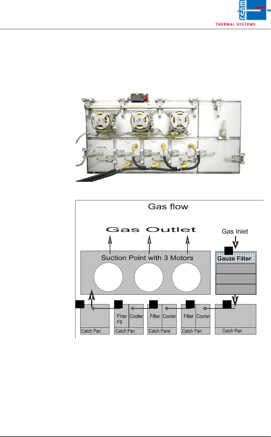
Fig. 2-69 Condensate Trap
Fig. 2-70 Condensate Trap Layout
Make sure that the following conditions have been fulfilled before working on
the condensate trap:
• Make sure that the fans are switched off and that water pressure has been
relieved with the help of the software. The “Cooling Tract Stopped” mes-
sage must appear at the monitor screen and the lock must be opened. Re-
fer to the “Main Window” subsection of the “Software” chapter in the
operating instructions to this end.
• Undo the water connections.
A
D C C BB