ServiceInstruction_Vision XP.pdf - 第69页
Vision XP+ V AC Page 65 3 Setup Instructions 3.1 Adjustment Operating Instructions V ersion 1.5 D) Relay T ype Enables cu rrent monitoring for th e entire conveyor adjustment system. E) Auto On/Off Automatic operation us…
Page 64 Vision XP+ VAC
3 Setup Instructions
3.1 Adjustment
Operating Instructions
Version 1.5
3.1 Adjustment
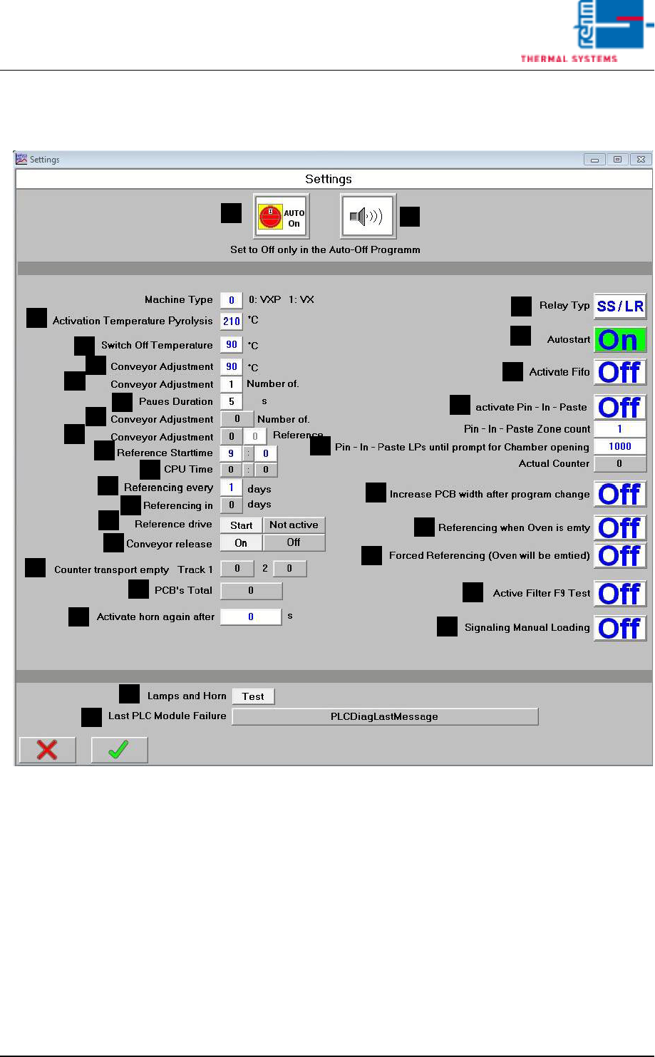
Fig. 3-2 Service Settings
System-specific settings are specified in this window.
A) Auto-Start-Switch
The drive unit, the heat, and compressed air can be turned on (auto-on)
of off (auto-off) simultaneously with this switch. the switch setting ist
stored to program memory.
B) Horn Switch
the horn sounds to indicate alarm messages which this switch is turned
on. If on the other hand, this switch is turned off, alarm messages appear
at the display only. The horn does not sound.
C) Temperature for pyrolysis activation
Only when a higher set value is preset in at least 2 peak-zones, the py-
rolysis is activated.
F
E
B
A
C
D
G
H
M
K
J
I
L
N
R
Q
P
O
S
T
U
V
W
X
Y
Z
AA
AB
AC
AD

Vision XP+ VAC Page 65
3 Setup Instructions
3.1 Adjustment
Operating Instructions
Version 1.5
D) Relay Type
Enables current monitoring for the entire conveyor adjustment system.
E) Auto On/Off
Automatic operation using the timetable (schedule), auto on/off software
button active or inactive.
F) Switch off temperature
This entry determines as of which temperature (for all active temperature
elements within the system) the shutdown routine is ended.
G) Conveyor Adjustment, °C
If actual temperature is less than the temperature selected here, neither
automatic nor manual conveyor adjustment can be activated.
H) Conveyor Adjustment, Number of Cycles
Number of adjusting cycles after loading a program (homing).
0 = homing deactivated.
1 = execute homing once a day (default setting)
2 to 254 = number of adjusting cycle for test purposes
255 = unlimited number of adjusting cycle for test purposes
I) Pause Duration
Pause in seconds before setpoints are activated during homing.
J) Conveyor Adjustment, Number of Cycles
Number of completed adjusting cycles
K) Conveyor Adjustment, Homing
Display and entry option for current homing progress. Homing can be
aborted by activating the emergency-stop button.
L) Reference Start time
Here the time is indicated when the reference run starts.
M) CPU Time
The current CPU time is indicated. By clicking the buttons in the margin
it can be updated.
N) Input field: reference run all n days
You can enter here if the reference run is daily (value), every other day
(value 2) or every three days (value 3).
O) Display field: reference run in n days
It is displayed here, in how many days there will be the next reference
run.
P) Reference Status
Over the button START the reference run can be started manually.
Reference Status:
-yellow: reference run will be carried out with the next program change.
-green: reference run will be carried out by activating the button refer-
ence.
Note!
As of now a reference run will be preset every 3 days at Rehm factory as a
standard. This is recommended by Rehm Thermal Systems.

Page 66 Vision XP+ VAC
3 Setup Instructions
3.1 Adjustment
Operating Instructions
Version 1.5
Q) Conveyor Release
To release the transportation push the button ON. The conveyor release
and CBS width can now be adjusted even if the system is cold.
Turn off the transportation release with Heating on, Heating off or Load
a program.
R) Display counter transport empty
It displays the residual number of the belt pulses, until the transport is re-
leased again (after the loading of the oven).
The counter can be reset over „Transport release IN“.
S) Total PCBs
Display of the total number of PCBs produced thus far.
T) Buzzer reactivation
If there is another value than 0, the buzzer is re-activated after the ac-
knowledgement on the alarm mask (after the specified time period in
sec.)
U) Fifo activation Activation / Deactivation of the Fifo - option (is described
in the operating manual)
V) Pin-In-Paste activation The button in the settings must be set on „On“,
when the option is shored. On the main mask there is a button for switch-
ing on/off of the function and the display „Pin-In-Paste OK“ or Pin-In-
Paste sheets exchanged.
W) Pin - IN - Paste:
Number of zones: Number of zones for Pin – In – Paste displayed
PCBs up to Open chamber request: Open chamber request when
switching Pin – In – Paste program to Pin – In – Paste program after pre-
set printed circuit board quantity. Warning issued when counter reaches
90% of the set number of PCBs.
Current counter status: Display of actual PCB’s processed.
X) Move the PCB-width apart after program change
If the function is activated, with program change the transport runs out
firstly to the max. value, in order that the boards, which could be in the
machine, fall in (only if in the new program the width is smaller as adjust-
ed before).
Y) Start reference when oven empty
After reference starting time, reference travel starts not only for program
change but also when oven is empty.
Z) Force reference travel (oven is run empty)
Reference travel starts at the set time (i.e. oven is disabled, emptied, ref-
erence travel and oven are then enabled again). Signal tower shows or-
ange during emptying.
AA)Filter test F9 during the reference run
If the key button is on „ON“, the filter F9 in the condensation trap is always
checked during the reference run.
AB)Signalling manual load
If the key button is on „ON“, the release for manual load is signalized over
the inlet interface.
AC)Signal tower and hooter
Test function for signal tower and hooter.