ServiceInstruction_Vision XP.pdf - 第98页
Page 94 Vision XP+ V AC 3 Setup Instructions 3.7 N2 Operating Parameters Operating Instructions V ersion 1.5 3.7 N2 Opera ting Para meters Fig. 3-1 2 N2 Pa rameters The mask is avai lable only in the sys tems with Siemen…
Vision XP+ VAC Page 93
3 Setup Instructions
3.6 Fan Parameters
Operating Instructions
Version 1.5
3.6 Fan Parameters
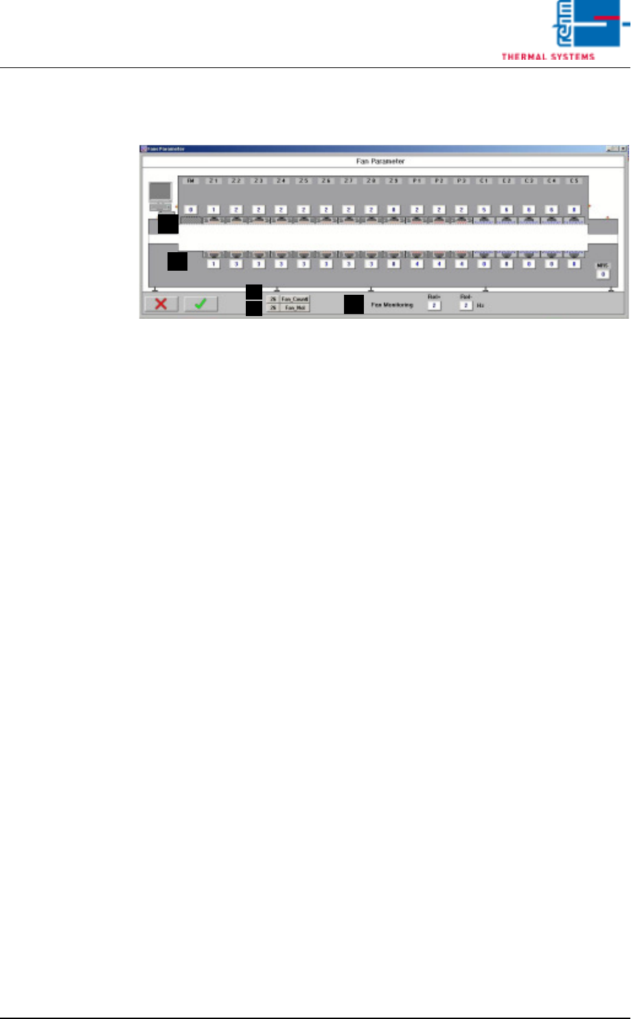
Fig. 3-11 Fan Parameters
The fan monitoring parameters are entered to this window.
A) Converter Assignment
Which fan will be controlled by which converter can be selected here.
0 = no fan, or fan monitoring not activated for this fan
1.16 = number of the desired frequency converter
20.60 = entry of a fixed frequency setpoint for this fan
B) Fan_Count
The number of defective fans is displayed here.
C) Fan_No.
The index number of the defective fan is displayed. In the event of more
than one defect, the highest index number is displayed.
D) Fan supervision
Input for tolerance of the fan supervision. Standard value is 2 Hz. When
exceeding the allocated frequency by 2 Hz an alarm fan supervision fail-
ure is triggered off.
C
B
A
A
D
Page 94 Vision XP+ VAC
3 Setup Instructions
3.7 N2 Operating Parameters
Operating Instructions
Version 1.5
3.7 N2 Operating Parameters
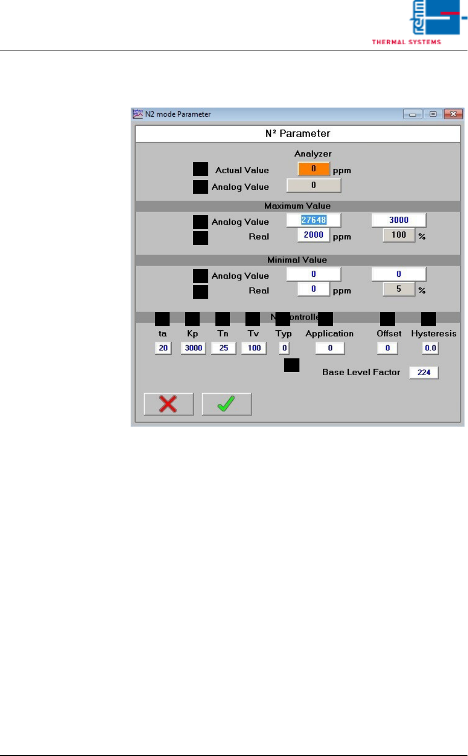
Fig. 3-12 N2 Parameters
The mask is available only in the systems with Siemens-Control.
Parameters for the N2 operating mode can be adjusted in this window.
A) Actual Value
Residual oxygen content display (optional). If the display field is empty,
the residual oxygen meter is switched off.
B) Analog Value (for S7 controller only)
The analog value which is currently being acquired from the analog input
is displayed here.
C) Analog Value, Maximum Values (for S7 controller only)
Acquired analog value (B) which corresponds to the actual value (D).
D) Actual Maximum Values (for S7 controller only)
Actual value which corresponds to the analog value (C).
E) Analog Value, Minimum Values (for S7 controller only)
Acquired analog value (B) which corresponds to the actual value (F).
F) Actual Minimum Values (for S7 controller only)
Actual value which corresponds to the analog value (E).
G) ta
Set sampling time.
C
D
B
A
E
F
MLKJIHG N
O

Vision XP+ VAC Page 95
3 Setup Instructions
3.7 N2 Operating Parameters
Operating Instructions
Version 1.5
H) Kp
Proportional component for the PID controller.
I) Tn
Integral component for the PID controller.
J) Tv
Differential component for the PID controller.
K) Type
Reserved for special applications.
L) Application
Reserved for special applications.
M) Offset
Deviation at the residual oxygen display can be compensated for with the
offset function.
N) Hysteresis
Tolerance evaluation performance can be adapted with the hysteresis
function.
O) Base Level Factor
• If the basic level factor is 0, the basic valve is actuated just like the
control valve.
• If the basic level factor lies within a range of 1 to 223, the basic valve
is coupled to the control valve via a filter function. Time „ta“ plays a
role in this respect. The duration of time during which filtering takes
place is calculated with the following formula
tf = ta x 100 ms x basic level factor
Example: ta = 20, basic level factor = 6 (time for mean value
generation)
tf = 20 x 100 ms x 6 = 12s
• If the basic level factor is 224 with a 6 bar valve or
if the basic level factor is 327 with a 2 bar valve,
the basic valve is actuated directly by means of the basic level.
• The entry under Base Level in the menu Masks is scaled with this
factor (submenu for N2 operating mode, see chapter 5.5.10 in the
operating instructions).