ServiceInstruction_Vision XP.pdf - 第48页
Page 44 Vision XP+ V AC 2 M aintenance 2.9 Cleaning the Exha ust Filters at the Inlet and the Outlet Operating Instructions V ersion 1.5 2.9 Cleaning the Exhau st Filter s at the In let and the Outlet Fig. 2-6 4 Pulling …
Vision XP+ VAC Page 43
2 Maintenance
2.8 Vacuum Unit
Operating Instructions
Version 1.5
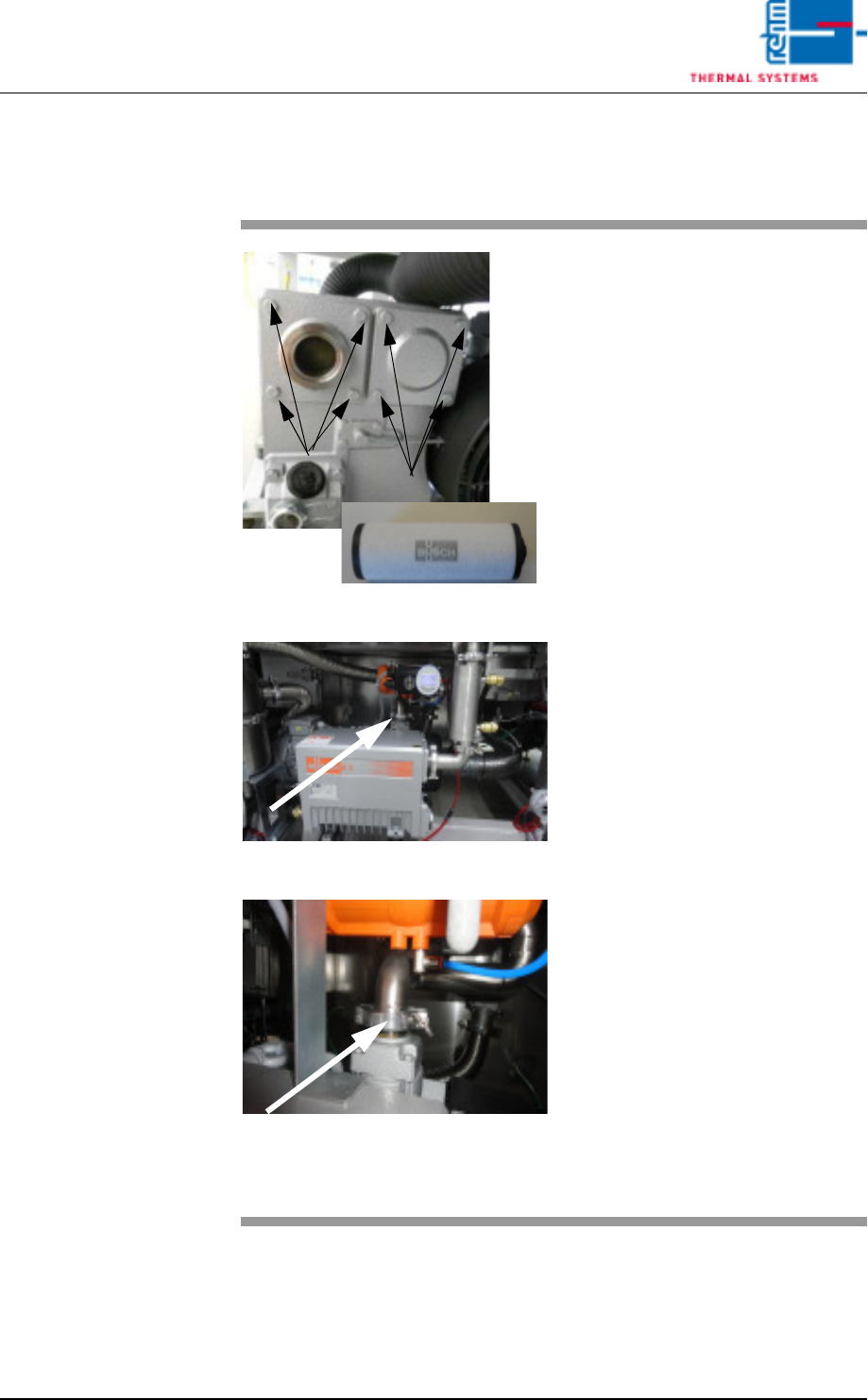
2.8.13 Clean the vacuum pump
Fig. 2-61 filter cartridges in the vacuum pump
Fig. 2-62 Pump
Fig. 2-63 Pump 1
Material:
• Filter cartridge 2 x
• Filter 1 x
1. Loosen the indicated screws to
replace the filter cartridges in
the vacuum pump.
2. Simply remove the covers to re-
place the cartridges.
3. Another filter is located in the in-
take connection.
4. Loosen the KF circlip, push the
tube aside and check the filter.
5. If heavily soiled, replace this fil-
ter also.
6. After replacement, reassemble
everything in reverse order.
Note!
Check the Fomblin filling level
every 4 weeks if the consumption
is high.
Page 44 Vision XP+ VAC
2 Maintenance
2.9 Cleaning the Exhaust Filters at the Inlet and the
Outlet
Operating Instructions
Version 1.5
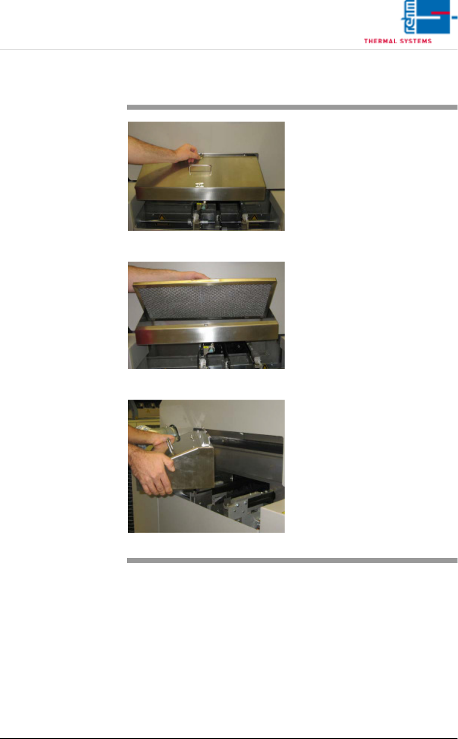
2.9 Cleaning the Exhaust Filters at the Inlet and the Outlet
Fig. 2-64 Pulling Out the Filter Housing
Fig. 2-65 Lifting the Filter Out of the Housing
Fig. 2-66 Lifting the Filter Housing
Consumable materials, tools:
• Oven cleaner
• Rags
• Or rinsing bath
Procedure:
1. Pull out the filter housing along
with the metallic gauze filter.
2. Loosen the wing screws and lift
the filter out of the filter housing.
3. Set the metallic gauze filter into
a rinsing bath. If a rinsing bath is
not available, the filter can be
cleaned with oven cleaner and
rags.
4. Lift the filter housing and set it
into a rinsing bath as well, or
clean it with oven cleaner and
rags.
5. After cleaning the filter, set it
back into the filter housing and
reinstall it into the system
Vision XP+ VAC Page 45
2 Maintenance
2.10 Water Tank - Checking and Refilling the Water
Fill-Level (Option)
Operating Instructions
Version 1.5
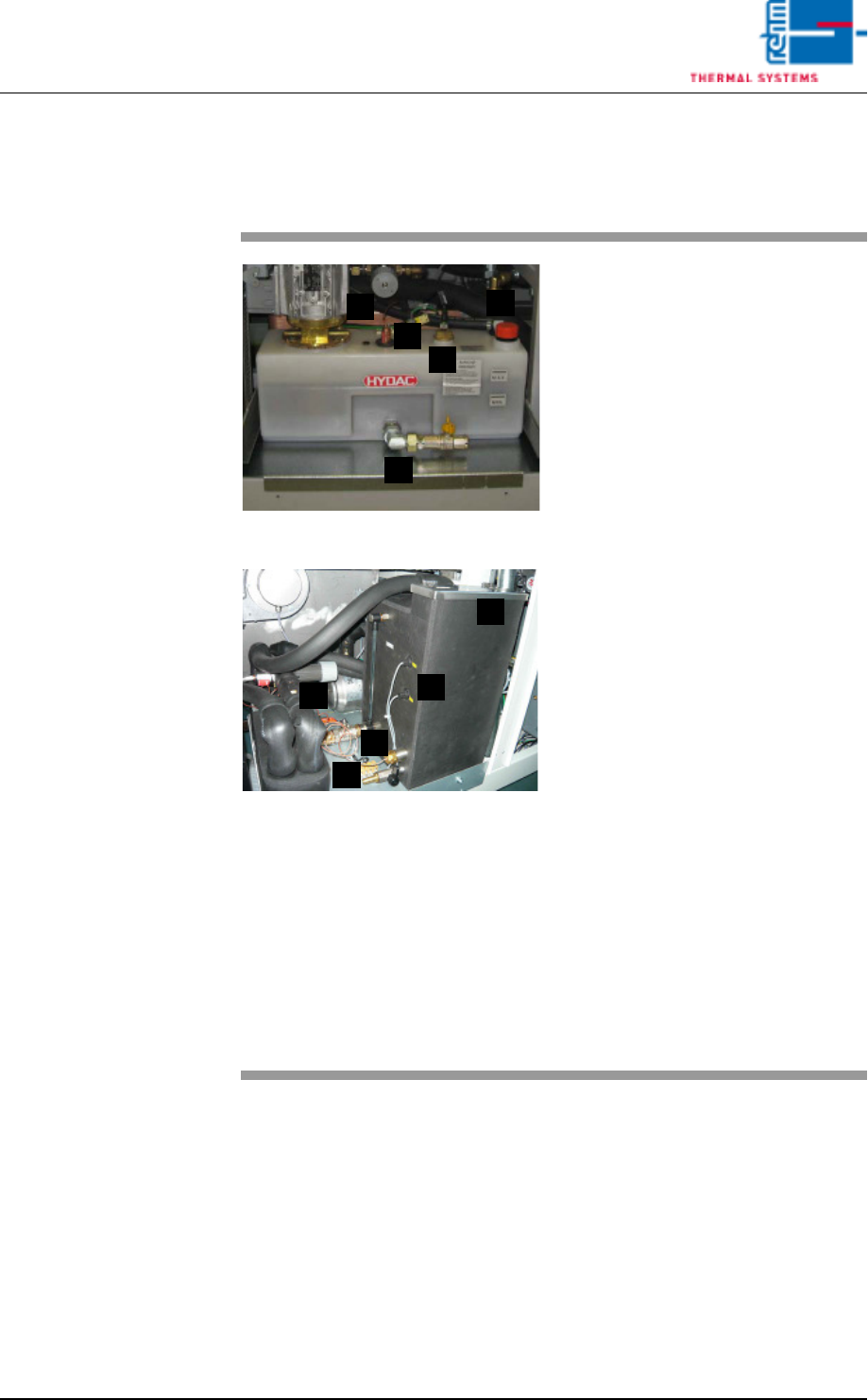
2.10 Water Tank - Checking and Refilling the Water Fill-Level (Op-
tion)
Fig. 2-67 Checking the Water Fill-Level
Fig. 2-68 Checking the Water Fill-Level, CN
The water tank is located behind the
second door from the right.
Consumable materials, tools:
• Water
• Antifreeze
Note!
Coolant is mixed using 1 part an-
tifreeze to 3 parts water.
• Watering can or similar container
Procedure:
1. The front of the water tank is
marked with the designations
MAX. and MIN.
2. When the fill-level drops to the
minimum mark, the tank must
be refilled with coolant to the
maximum mark.
3. For re-filling open the filling port
(D) at the tank and fill in the
mixed cooling liquid.
Cooling system components:
A) Cooling water controller
B) Water leak and minimum water
level sensor
C) Connection for draining water
D) Filling port
E) Temperature watchdogs
A
B
C
D
E
A
C
E
B
D