4H4CEPM.pdf - 第31页
Page 21 301 CM Chip Data 4H4C-E-PMA01-A02-01 2. Lead float check information Edit the information about the lead float check. <Lead float check> Specify whether to check the lead float. (T o check the lead float, t…
Page 20
444C-EPt-EdCl-013
Chip Data
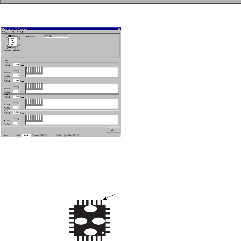
3-3 QFP Chip
1. Side No.
2. Pin Information
∗ PinPitch
∗ ActualPin (Number of actual pins)
∗ PlanPin (Number of provisional pins)
1. Side No.
When you look down at a chip at 0° of its packing form, the bottom side is the 1st side and then the
2nd side, the 3rd side, the 4th side clockwise. As to the pin No., the leads on the 1st side are called
1, 2, 3 ..... from right to left. Those on the 2nd side are called so from bottom to top, those on the
3rd side are called so from left to right and those on the 4th side are called so from top to bottom.
For example, this lead is the 6th pin on the 3rd side.
1side
1
2
3
4
4321
4
3
2
1
3side
2side 4side
Input the data of the chip at 0° of its packing form.
444C-014E
4H4C-E-PMA01-A02-00
Page 21
301
CM
Chip Data
4H4C-E-PMA01-A02-01
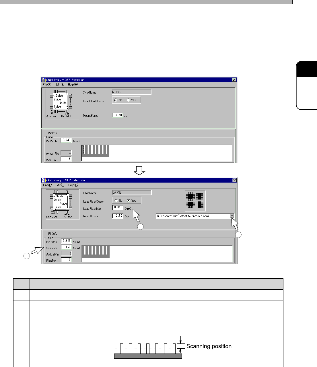
2. Lead float check information
Edit the information about the lead float check.
<Lead float check>
Specify whether to check the lead float.
(To check the lead float, the optional lead checker is required on the machine.)
Selecting “Yes” changes the window as follows. Set the items displayed newly.
3. Mounting load
Type what load will be applied for mounting.
4H4C-EPt-EdCl-011
4H4C-EPt-EdCl-012
.oN emaN noitcnuF
1noitingocerresalrofepytCI noitingocerresalehthtiwhsiugnitsidotepytCIehtesoohC
2xaMtaolfdaeL .gnitnuomrofelbawollaeblliwtaolffohtgneltahwotepyT
.detnuomebtonlliwecnarelotehtgnideecxepihcehT
3gninnacsresaL .pitnipehtmorfderusaem,taolfdaelehtkcehcoterehwepyT
)edishcaerofsihttupnI(
4H4C-007TE
9Q4C-037TE
1
2
3
Page 22
PlanPin (Number of provisional pins)
ActualPin (Number of actual pins)
Pin No.
Missing pin information
Chip Data
4. Pin Information
∗∗
∗∗
∗ PinPitch
∗∗
∗∗
∗ ActualPin (Number of actual pins)
∗∗
∗∗
∗ PlanPin (Number of provisional pins)
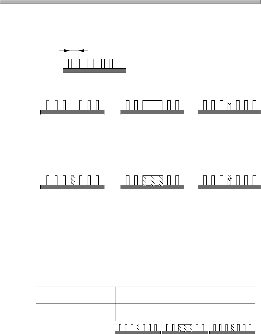
As to SOP, QFP, etc., leads of the same width are aligned at the same pitches generally.
But there are the following exceptions, too.
In such cases, the program must be set not to search for the tips of the leads at those positions
during image processing. Therefore, register the position where a lead does not exist as “missing
pin.”
When you register the position of the missing pin, the notion of “provisional pins” is used.
Suppose there are leads at the same pitches even when some leads are missing and so on, and
number the imaginary leads. This line of leads including imaginary leads is called “provisional pins.”
Among them, the leads which actually exist are called “actual pins.” ( “provisional pins” = “imagi-
nary leads” + “actual pins (the leads which actually exist)” )
Then, register the positions of the imaginary leads using the pin No.
When data is created, the position of the actual pin is represented by O and that of imaginary lead
is represented by ×. This data is called “missing pin information.” And the number of actual pins is
called “ActualPin,” that of provisional pins is called “PlanPin.”
444C-015E
Pitch
A lead is missing due
to the chip designing.
A radiation panel is
between leads.
A frame mark is
between leads.
1234567 1234567 1234567
Suppose there is an
imaginary lead at the
position of the missing pin.
Suppose there are imagi-
nary leads at the position of
the radiation panel.
Suppose there is an
imaginary lead at the
position of the frame mark.
444C-016E
444C-017E
1
O
7
6
2
O
3
O
4
×
5
O
6
O
7
O
1
O
7
4
2
O
3
×
4
×
5
×
6
O
7
O
1
O
7
6
2
O
3
O
4
×
5
O
6
O
7
O
4H4C-E-PMA01-A02-01