4H4CEPM.pdf - 第36页
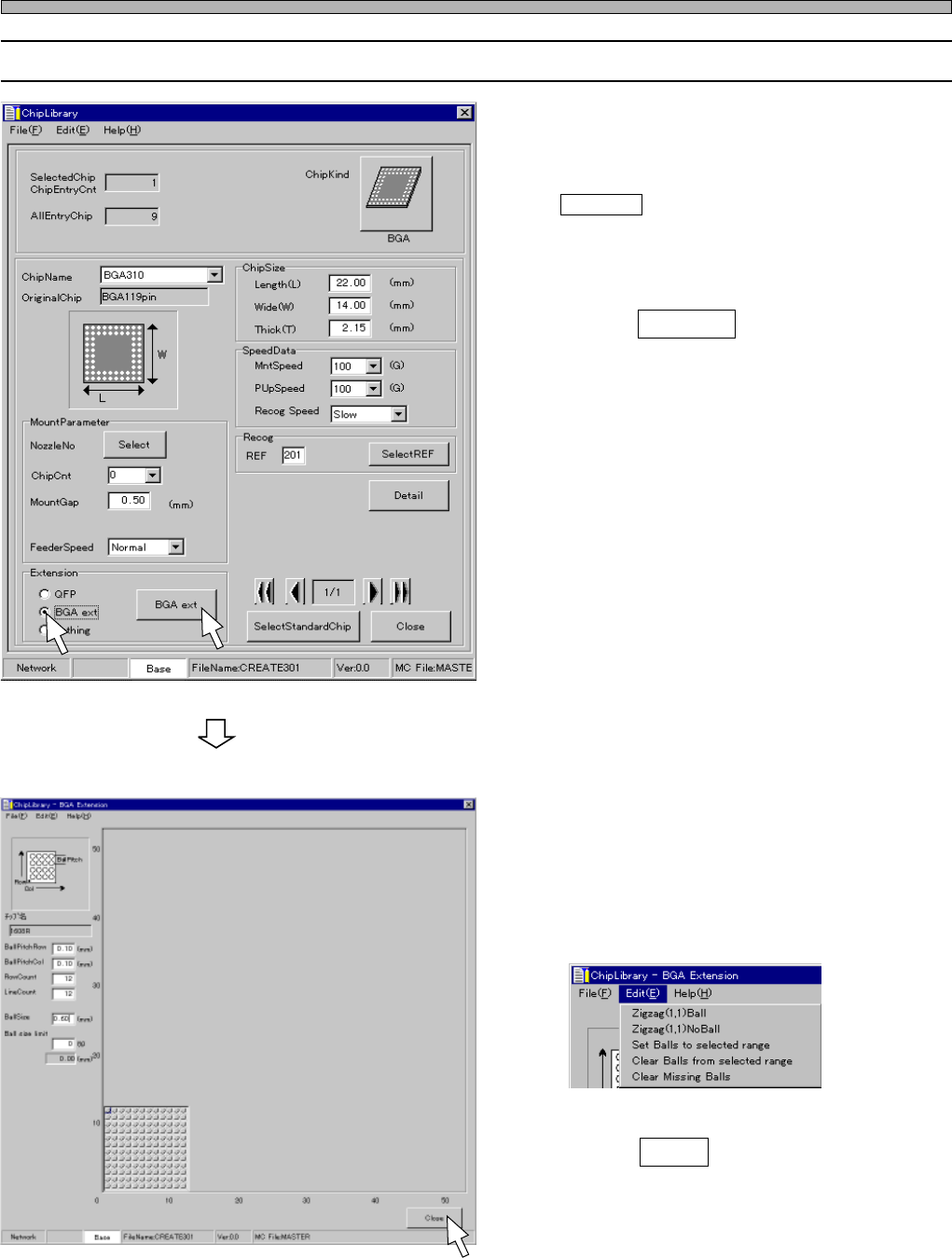
Page 26 Chip Data 3-6 Editing BGA Chip 1. Click on the radio button of “BGA ext”. • BGA ext switch is displayed. 2. Click on BGA ext . • [BGA Extension] window opens. 3. Enter the RowCount, LineCount, Ballsize and Ball s…
Page 25
301
CM
Chip Data
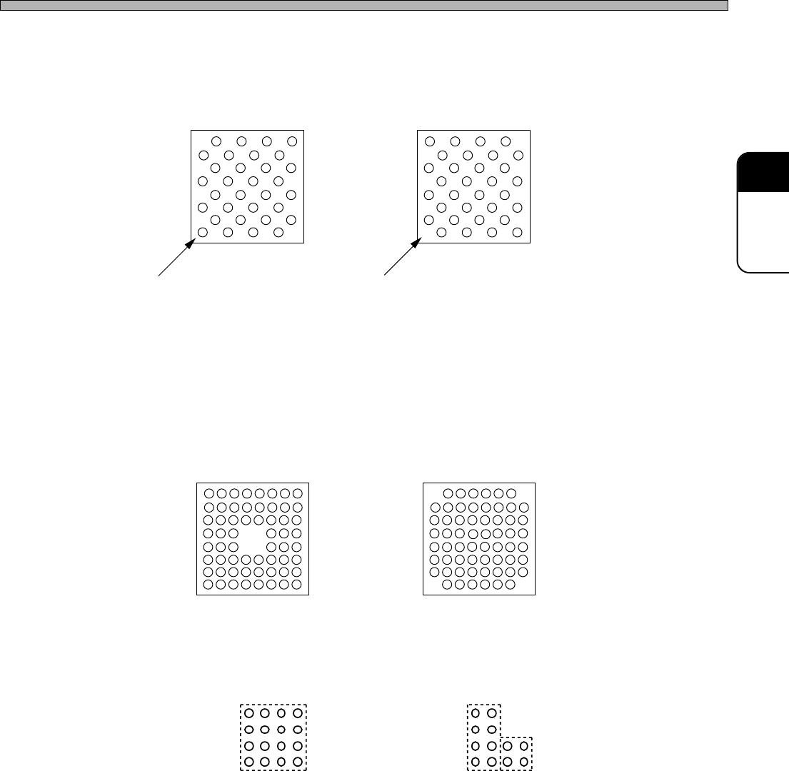
4. Zigzag Arrangement / Missing Balls Setting
Zigzag Arrangement
Fig. 2 (A) and (B) show the cases that balls are arranged zigzag.
On CM301, you can set a zigzag arrangement at a time.
Missing Balls Setting
To create the arrangement as shown at Fig. 3, create the arrangement as shown at Fig. 1 first. And
then, set the missing balls, because CM301 is programmed to judge the arrangement as shown at
Fig. 3 is created by removing four balls at the center from the arrangement as shown at Fig. 1.
Some types of BGA and CSP do not have balls at each corner as shown at Fig. 4. In this case also,
use the same steps as that for Fig. 3. You can set one group of missing balls at a time. Therefore,
when setting missing balls at four corners, you need to repeat setting them four times.
If a group of missing balls can not be enclosed by one square, you need to divide them into two or
more groups to set. For example, missing balls as shown at Fig. 5 (A) can be set as one group, but
those as shown at Fig. 5 (B) should be set as two groups.
Fig. 3 Fig. 4
444C-018E
Fig. 5 (A) Missing balls can be
enclosed by one square.
Fig. 5 (B) Two squares are required
to enclose missing balls.
Fig. 2 (A)
Ball exists at (1, 1).
Fig. 2(B)
Ball does not exist at (1, 1).
4H4C-E-PMA01-A02-01
Page 26
Chip Data
3-6 Editing BGA Chip
1. Click on the radio button of “BGA
ext”.
• BGA ext switch is displayed.
2. Click on BGA ext .
• [BGA Extension] window opens.
3. Enter the RowCount, LineCount,
Ballsize and Ball size limit.
• When balls are arranged zigzag or some balls
are missing, click on “Edit” on the menu bar
and set them.
4. Click on Close .
• [ChipLibrary] window opens.
444C-EPt-EdCl-019
4H4C-EPt-EdCl-010
4H4C-EPt-EdCl-009
4H4C-E-PMA01-A02-02
Page 27
301
CM
4 Nozzle Data
4-1 Nozzle Data
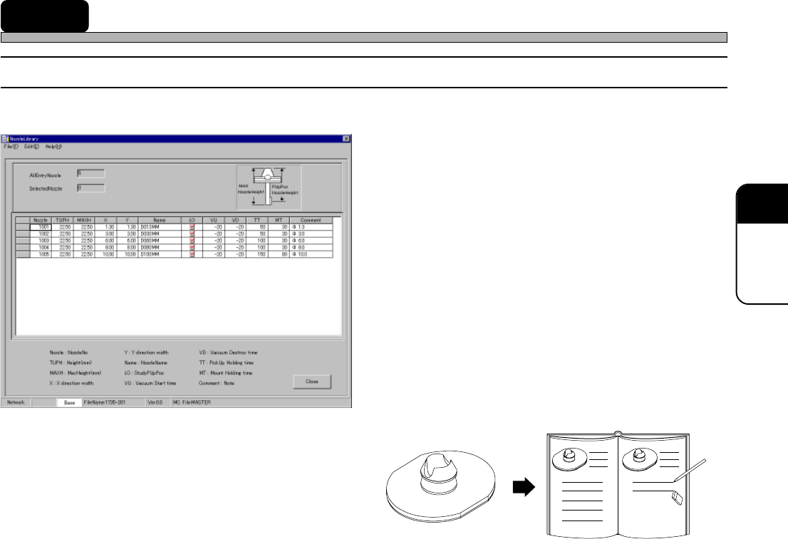
Custom nozzle library
1. Nozzle : Nozzle No.
2. TUPH : Nozzle Height (mm)
3. MAXH : Maximum Nozzle Hieght (mm)
4. X : Length in the X-axis Direction
(mm)
5. Y : Length in the Y-axis Direction
(mm)
6. Name : Nozzle Name
7. LO : Enabling/Disabling Pick-up
Position Learning
8. VU : Vacuum Rise Time (ms)
9. VD : Vacuum Break Time (ms)
10. TT : Pick-up Holding Time (ms)
11. MT : Mount Holding Time (ms)
12. Comment : Comment
1. Nozzle No.
Indicates a nozzle recognition No.
2. Nozzle Height (mm)
Indicates the height from the top of the
nozzle to a pick-up surface.
3. Maximum Nozzle Height (mm)
Indicates the overall height of the nozzle.
∗ This is supported when the tip of the nozzle is below a pick-up surface.
The maximum nozzle height of the standard nozzle is 22.5 mm. However, if the value of the pick-up
position Z becomes lower than -3.00 mm, the special nozzle is required so as not to interfere with
the adjoining feeders.
4. Length in the X -axis Direction (mm)
Indicates the length in the X-axis direction when the nozzle is seen from its top.
5. Length in the Y -axis Direction (mm)
Indicates the Iength in the Y-axis direction when the nozzle is seen from its top.
6. Nozzle Name
Indicates the name of the nozzle.
7. Enabling/Disabling Pick-up Position Learning
Indicates whether or not the pick-up position learning is performed.
444C-602E
4H4C-EPt-EdNl-001
4H4C-E-PMA01-A02-01