4H4CEPM.pdf - 第42页
Page 32 6 Board Data 6-1 Board Data 1. BoardSize 2. Coordinates 3. OriginOffset 4. BadBoardMarkPos 5. Mnt End chip Max T The descriptions are as follows. 1. BoardSize The length of the surface parallel to board flowing d…
Page 31
301
CM
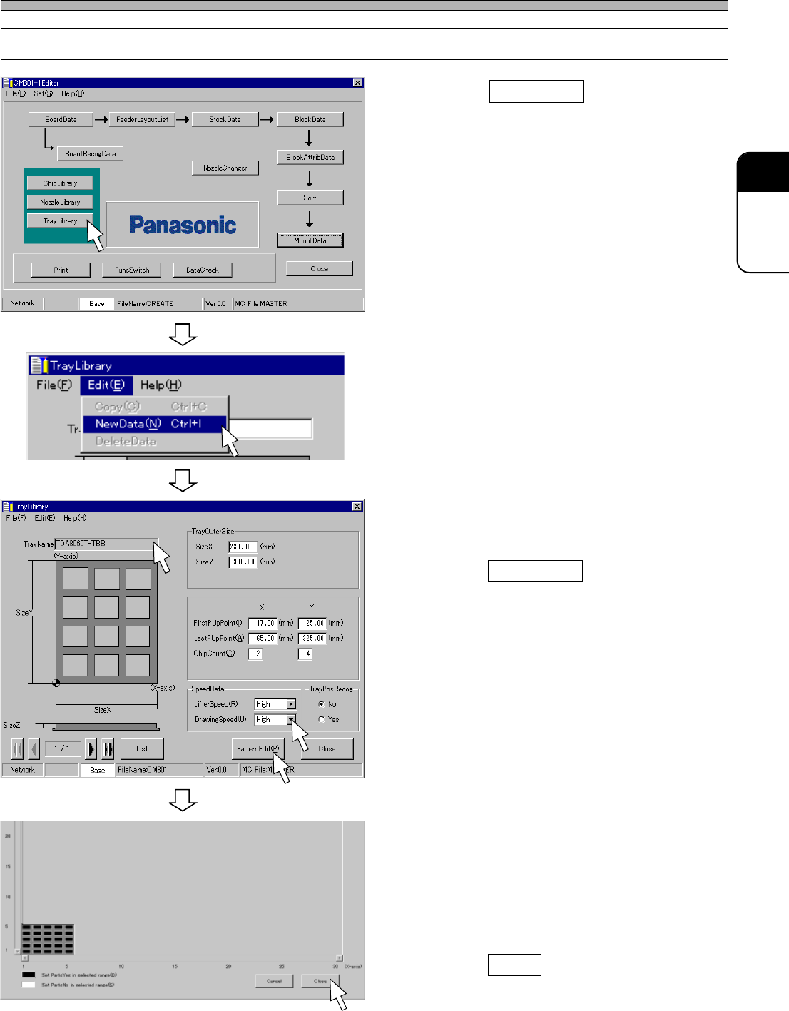
5-2 Editing Tray Data
1. Click on TrayLibrary .
• [TrayLibrary] window opens.
2. Choose “NewData” from “Edit” on the
menu bar.
3. Enter from TrayName to SpeedData in
due order.
4. Click on PatternEdit .
• [TrayPartsMissingPatternEdit] window opens.
5. Set the chip arrangement by the
pattern edit.
∗ You can set a zigzag arrangement by just
choosing “Edit” > “Zigzag(1,1)PartsYes” or
“Zigzag(1,1)PartsNo” on the menu bar.
6. Click on Close .
• The main menu is displayed.
4H4C-E-PMA01-A03-03
Tray Data
4H4C-EPt-Ed-001
4H4C-EPt-EdTl-002
4H4C-EPt-EdTl-004
4H4C-EPt-EdTl-003
Page 32
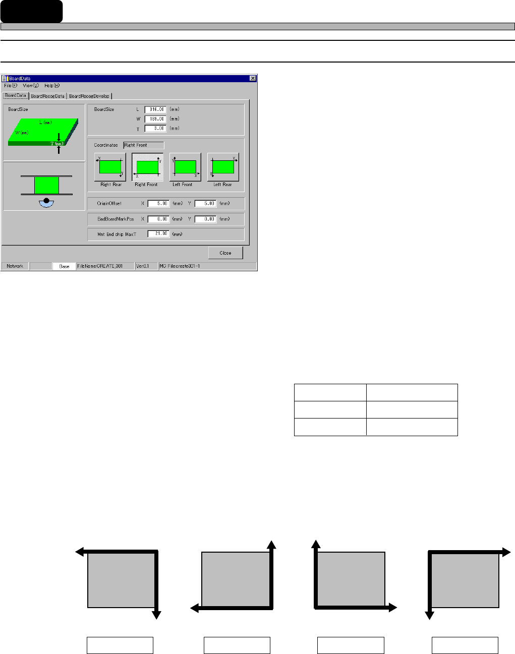
6 Board Data
6-1 Board Data
1. BoardSize
2. Coordinates
3. OriginOffset
4. BadBoardMarkPos
5. Mnt End chip Max T
The descriptions are as follows.
1. BoardSize
The length of the surface parallel to board flowing direction is L (mm), that vertical to it is W (mm)
and the thickness of the board is T (mm).
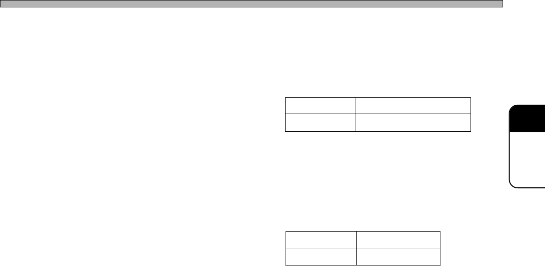
2. Coordinates
Choose datum coordinates on the board from among Right Rear, Right Front, Left Front and Left
Rear.
Each direction of the coordinate axis is as follows.
All the coordinates on the board are represented on the basis of Coordinates (set in this step.) and
OriginOffset (set in the next step.)
4H4C-E-PMA01-A03-03
4H4C-EPt-EdBd-002
X
Y
X
Y
X
Y
X
Y
Front side Front side Front side Front side
Right Rear Right Front Left Front Left Rear
433C-078E
50 mm to 460 mm
50 mm to 360 mm
0.5 mm to 3.0 mm
Input Limits
L (Length)
W (Width)
T (Thickness)
Page 33
301
CM
3. OriginOffset
By default, the origin of Coordinates is at the corner of the board. But you can move it by entering
OriginOffset. The range of the value to input in OriginOffset is as follows.
4. BadBoardMarkPos
When using the defective board detecting function, enter the coordinates of the defective board
mark.
5. Mnt End chip Max T
Enter the maximum height of the chip mounted at the previous process so as not to interfere a
nozzle or the chip that is picked up by a nozzle with the mounted chips at during mounting.
- 20 to the board size L
4H4C-E-PMA01-A03-03
Board Data
Input Limits
Input Limits
0 mm to 460 mm
0 mm to 360 mm
X
Y
X
Y
- 20 to the board size W