4H4CEPM.pdf - 第80页
Page 70 Mount Data 7. BL This is the block No. set in block attribute data. 8. No. This shows a descriptive order in block data. ( 1 1-1 ) 9. Priority Comparing the mount point with the other ones, you can specify whethe…
Page 69
301
CM
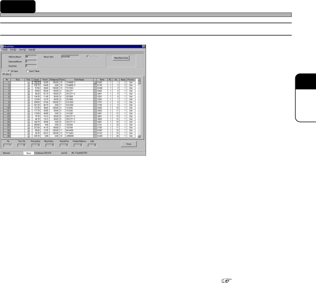
14 Mount Data
14-1 Mount Data
1. Skip (Information)
2. Skip (Setting)
3. X (mm), Y (mm)
4. A (Degree)
5. PartsName
6. Note
7. BL
8. No.
9. Priority
10. MR
11. Mounted Info
12. sort flag
13. No
14. Turn No
15. PickupSeq
16. MountSeq
17. NozzlePos
18. FeederAddress
19. side
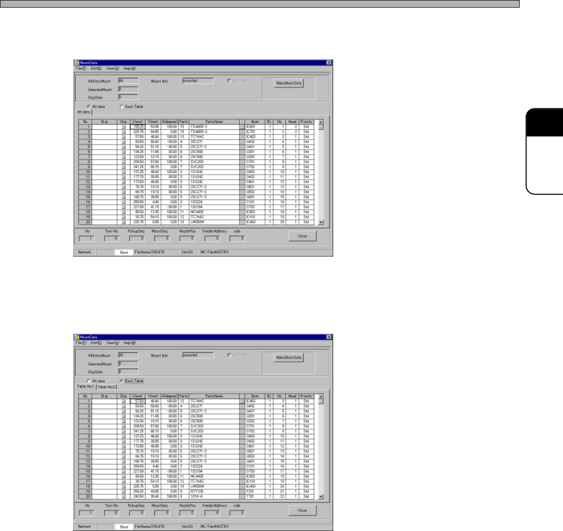
20. All data
21. Each Table
The descriptions are as follows.
1. Skip (Information)
When Skip has been set in the feeder layout list, “USKP” is displayed in this field. When Skip has
been set in block data, “BSKP” is displayed in this field. When Skip has been set in mount data,
“MSKP” is displayed in this field.
2. Skip (Setting)
When there is the data you do not want to mount temporarily, you can Skip that data.
∗ This Skip function differs from that of feeder layout list or block data. ( 8-1)
3. X (mm), Y (mm)
Enter the coordinates of the mount point. See “11-1 Block Data” to find the coordinates.
4. A (Degree)
Enter the mount angle of the chip. See “11-1 Block Data” to find it.
5. PartsName
PartsName registered in the feeder layout list is displayed.
6. Note
The comment registered in block data is displayed.
4H4C-E-PMA01-A05-03
4H4C-EPt-EdMo-001

Page 70
Mount Data
7. BL
This is the block No. set in block attribute data.
8. No.
This shows a descriptive order in block data. ( 11-1)
9. Priority
Comparing the mount point with the other ones, you can specify whether to mount the chip at this
mount point earlier or later. For example, this is used to mount chips under the large chip.
10. MR
MR indicates whether mount point recognition is performed or not. To perform mount point
recognition, the mount point recognition data must be created.
11. Mounted Info
Whether the modular sort is executed is displayed. When it is executed, the information on the
sequence of the chosen data.
12. Sort flag
It is possible to clear the modular sort information. When it is cleared, the machine determines the
mount order automatically.
13. No
This shows the row No. of mount data. It does not show the mount sequence.
14. Turn No (Turn No. for each board)
In which turn the chip will be mounted is displayed. It is counted for each head while regarding
pick-up-recognition-mounting as one turn.
15. PickupSeq
This shows the pick-up order in each turn. (1 to 2)
16. MountSeq
This shows the mount order in each turn. (1 to 2)
17. NozzlePos
This shows the nozzle arrangement No. (1 to 2)
18. FeederAddress
This shows the address where the parts are set by using five-digit number. The first and second
numbers from the bottom show the address. The fifth one shows table No. The third one is always
0. The forth one indicates the distinction between right and left of the direct twin tray feeder.
19. side
This indicates in which lane the stick is set when the vibratory feeder is used.
4H4C-E-PMA01-A05-03
Page 71
301
CM
4H4C-E-PMA01-A05-03
Mount Data
20. All data
When ticking off “All data”, the mount data to be mounted at all the tables is displayed.
21. Each Table
When ticking off “Each Table”, the mount data for each table is displayed.
4H4C-EPt-EdMo-001
4H4C-EPt-EdMo-006