4H4CEPM.pdf - 第34页
Page 24 Chip Data 3-5 BGA Chip 1. Ball Pitch Line / Ball Pitch Row 2. RowCount / LineCount 3. Ballsize / Ball size limit 4. Zigzag Arrangement / Missing Balls Setting 1. Ball Pitch Line / Ball Pitch Row These show the li…
Page 23
301
CM
444C-EPt-EdCl-014
Chip Data
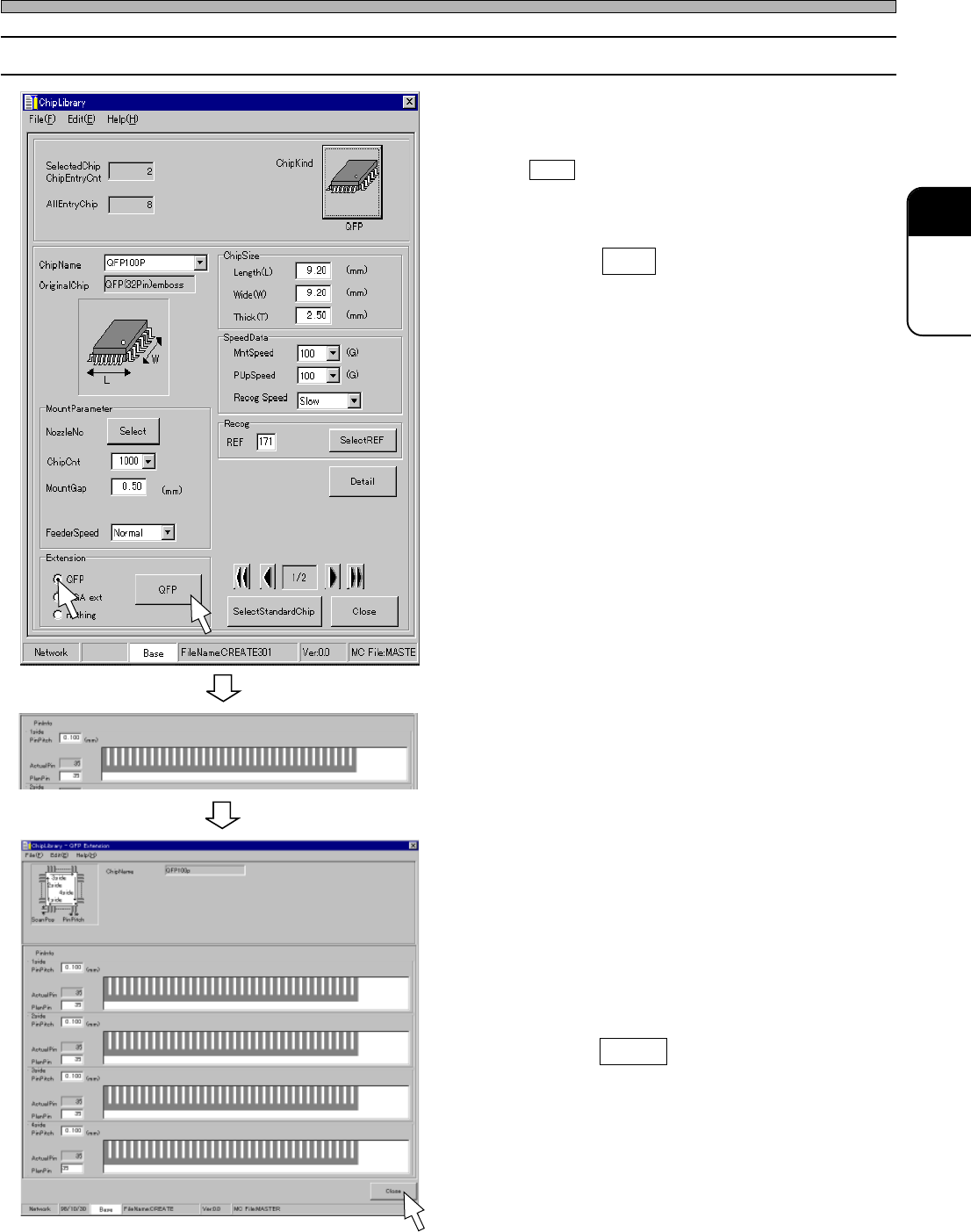
3-4 Editing QFP Chip
1. Click on the radio button of “QFP.”
• QFP switch is displayed.
2. Click on QFP .
• [QFP Extension] window opens.
3. Enter the PinPitch and PlanPin.
• Pins are displayed.
4. Repeat step 3. until you finish enter-
ing the information of 4side.
5. Enter the actual pins arrangement.
∗ When ActualPin is not the same as
PlanPin,click the missing pin position(s).
6. Click on Close .
• [ChipLibrary] window opens again.
444C-EPt-EdCl-014
4H4C-EPt-EdCl-008
4H4C-E-PMA01-A02-01
Page 24
Chip Data
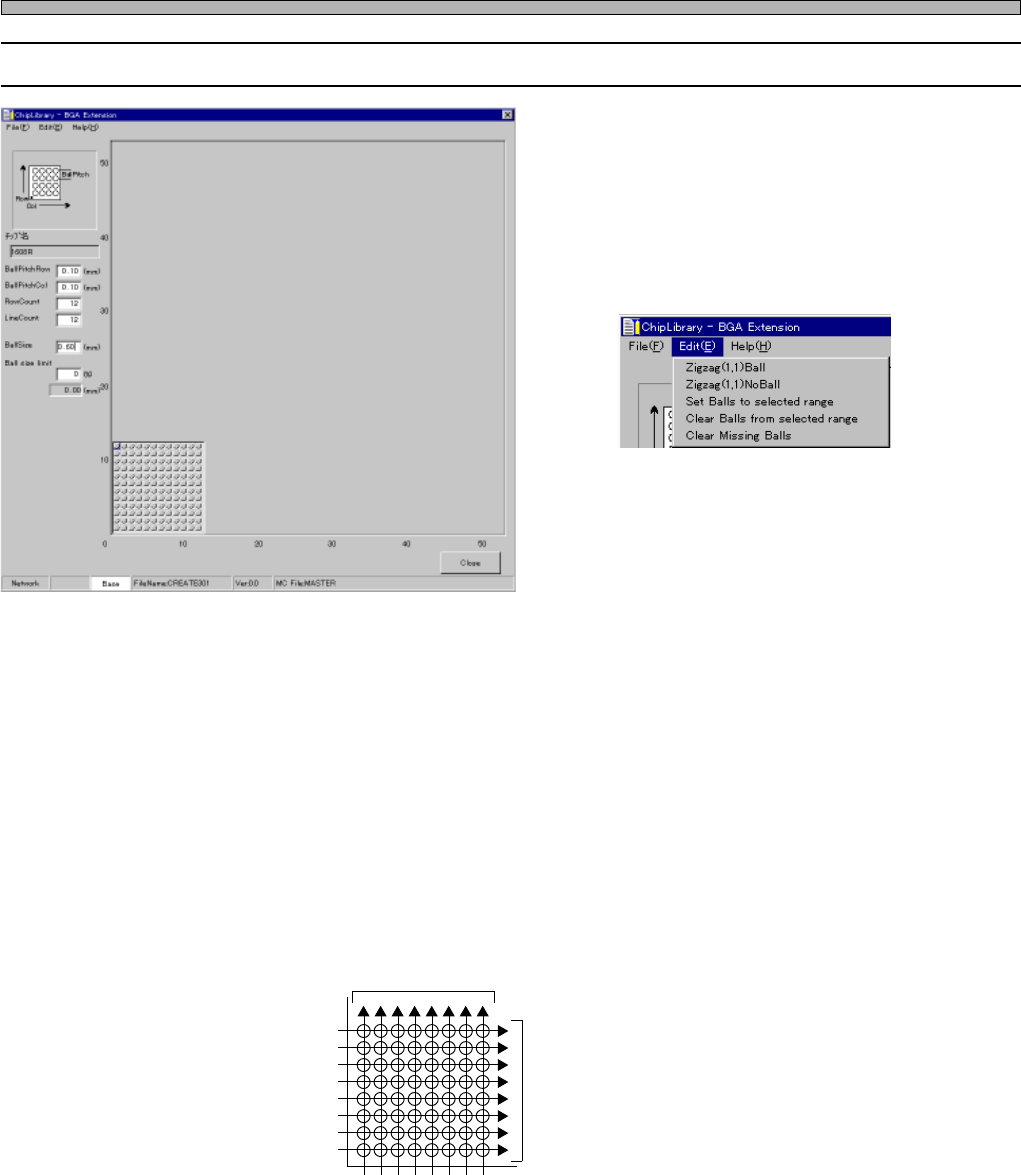
3-5 BGA Chip
1. Ball Pitch Line / Ball Pitch Row
2. RowCount / LineCount
3. Ballsize / Ball size limit
4. Zigzag Arrangement / Missing Balls
Setting
1. Ball Pitch Line / Ball Pitch Row
These show the line and row pitches of balls.
2. RowCount / LineCount
These show the number of balls per row and the number of balls per line.
The positions of the balls of BGA and CSP are indicated by the combination of the line No. and row
No. When you look down at the balls side of BGA or CSP with the index corner placed at the lower
left, a horizontal alignment is called “Row” and a vertical one is called “Line”.
3. Ballsize / Ball size limit
Ballsize : This shows the diameter of the part shining on the screen.
Ball size limit : This shows the percentage that the recognition on the basis of ball’s diameter is
OK. (The range of OK is Ballsize ± Ball size limit.)
Row No.
Line No.
Fig. 1
Line
Row
1 2 3 4 5 6 7 8
1
2
3
4
5
6
7
8
444C-EPt-EdCl-019
4H4C-EPt-EdCl-009
4H4C-E-PMA01-A02-01
Page 25
301
CM
Chip Data
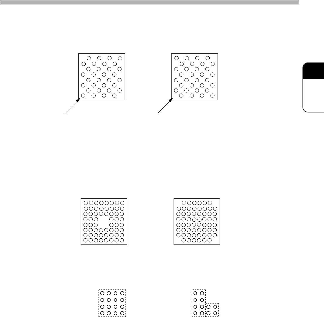
4. Zigzag Arrangement / Missing Balls Setting
Zigzag Arrangement
Fig. 2 (A) and (B) show the cases that balls are arranged zigzag.
On CM301, you can set a zigzag arrangement at a time.
Missing Balls Setting
To create the arrangement as shown at Fig. 3, create the arrangement as shown at Fig. 1 first. And
then, set the missing balls, because CM301 is programmed to judge the arrangement as shown at
Fig. 3 is created by removing four balls at the center from the arrangement as shown at Fig. 1.
Some types of BGA and CSP do not have balls at each corner as shown at Fig. 4. In this case also,
use the same steps as that for Fig. 3. You can set one group of missing balls at a time. Therefore,
when setting missing balls at four corners, you need to repeat setting them four times.
If a group of missing balls can not be enclosed by one square, you need to divide them into two or
more groups to set. For example, missing balls as shown at Fig. 5 (A) can be set as one group, but
those as shown at Fig. 5 (B) should be set as two groups.
Fig. 3 Fig. 4
444C-018E
Fig. 5 (A) Missing balls can be
enclosed by one square.
Fig. 5 (B) Two squares are required
to enclose missing balls.
Fig. 2 (A)
Ball exists at (1, 1).
Fig. 2(B)
Ball does not exist at (1, 1).
4H4C-E-PMA01-A02-01