4H4CEPM.pdf - 第68页
Page 58 4H4C-E-PMA01-A04-02 X Y X Y X Y X Y 1 Right Rear 2 Left Rear Origin (0,0) Central point of chip (X,Y) Central point of chip (X,Y) Origin (0,0) 3 Right Front 4 Left Front Central point of chip (X,Y) Central point …
Page 57
301
CM
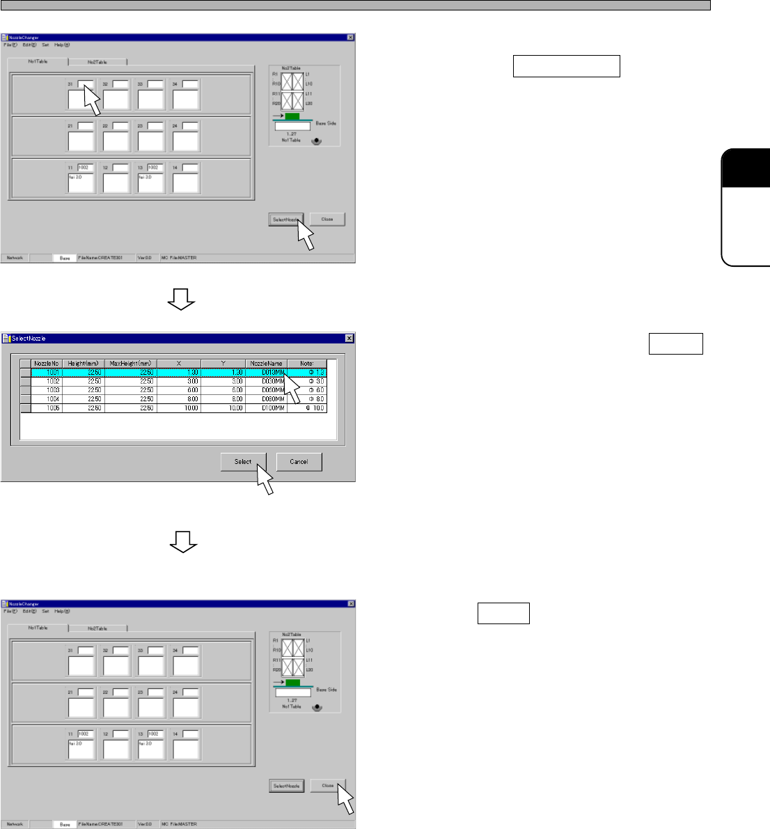
2. Choose a table No. and a nozzle No.,
then click on SelectNozzle .
• [SelectNozzle] window opens.
3. Choose a nozzle, and click on Select .
• The nozzle is registered.
4. Register all nozzles by repeating the
steps from 2. to 3.
5. Click on Close .
• The main menu is displayed.
Nozzle Changer Data
4H4C-E-PMA01-A04-02
4H4C-EPt-EdNs-001
4H4C-EPt-EdNs-002
4H4C-EPt-EdNs-003
Page 58
4H4C-E-PMA01-A04-02
X
Y
X
Y
X
Y
X
Y
1
Right Rear
2
Left Rear
Origin (0,0)
Central point of chip (X,Y)
Central point of chip (X,Y)
Origin (0,0)
3
Right Front
4
Left Front
Central point of chip (X,Y)
Central point of chip (X,Y)
Origin (0,0) Origin (0,0)
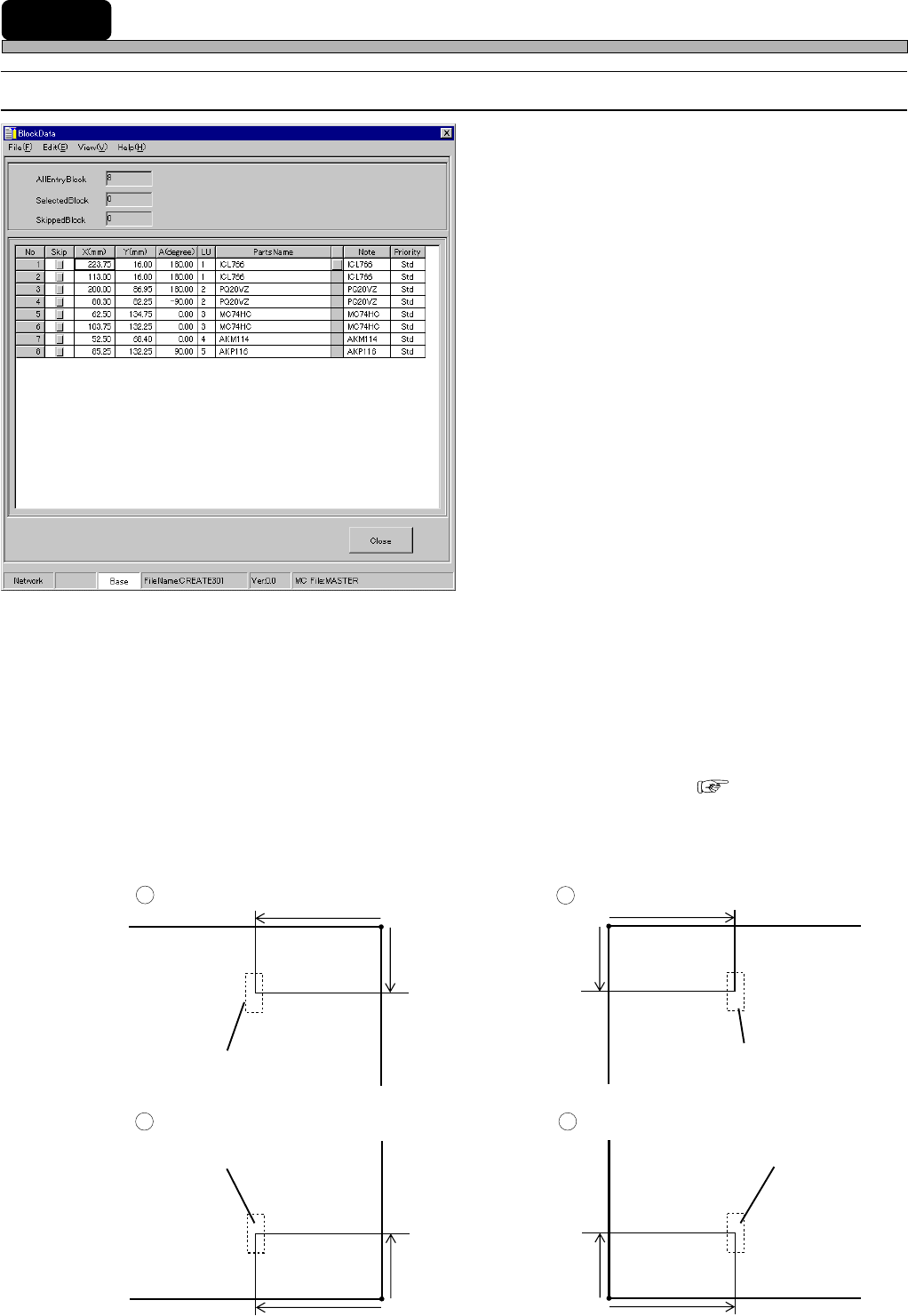
11 Block Data
11-1 Block Data
1. No.
2. Skip
3. X (mm), Y (mm)
4. A(degree)
5. PartsName
6. Note
7. Priority
The descriptions are as follows.
1. No.
This shows the descriptive order of mount points in block data. Actual mount order is determined by
sort, then mount data are created.
2. Skip
When there is a mount point on which you do not want to mount a chip temporarily, you can Skip
that mounting point.
∗ This Skip function differs from that of feeder layout list or mount data. ( 8-1)
3. X (mm), Y (mm)
Enter the coordinates of each mount point. The coordinates are represented on the basis of
Coordinates and OriginOffset in board data.
4H4C-EPt-EdBl-001
Page 59
301
CM
4H4C-E-PMA01-A04-02
Block Data
4. A(degree)
Enter the mount angle of each mount point.
5. PartsName
PartsName registered in the feeder layout list is displayed.
6. Note
You can enter the comment on each mount point. For example, when you enter the chip ID No. on
the pattern of the board, it will be easy to collate chips with the data.
7. Priority
Comparing the mount point with the other ones, you can specify whether to mount the chip at this
mount point earlier or later. For example, this is used to mount chips under the large chip.
AB
+-
180°
135°
90° 45° 0° -45° -90° -135°
-180°
+
+
+
+
+
+
+
+
+
ノズルチェンジャノズルチェンジャ
• The angle of the chip A is -180°, 0° or 180°.
• The angle of the chip B is -180° or 180°.
4H4C-614E
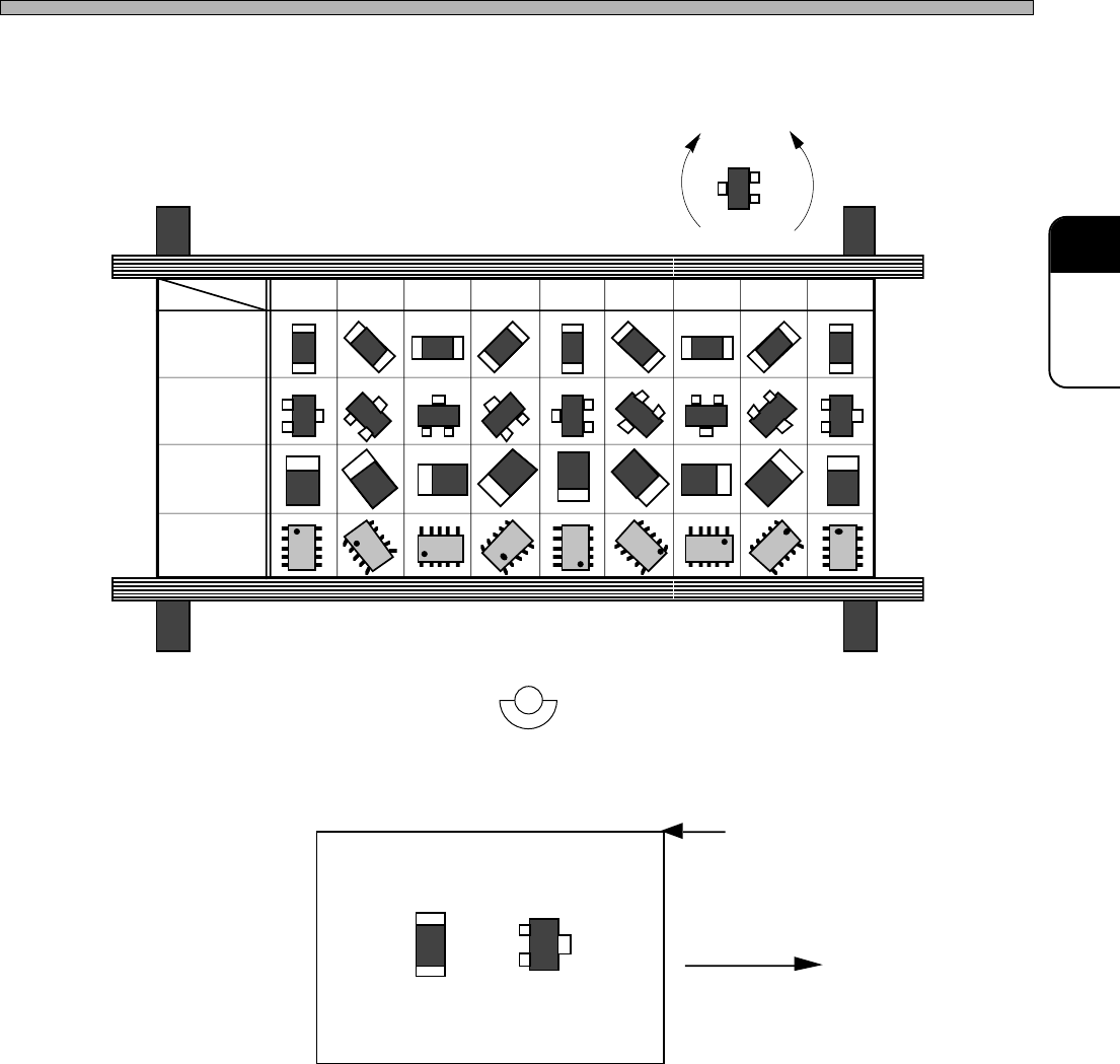
Flowing Direction
Origin of Mount Coordinates
Board
Non-
polarized
square chip
Transistor
Tantalum
capacitor
SOP
0.1° unit
Angle
Chip
Front Side