4H4CEPM.pdf - 第44页
Page 34 6-2 Editing Board Data 1. Click on BoardData . • [BoardData] sheet on [BoardData] window opens. 2. Enter BoardSize. • Enter the board size L, W , T . 3. Choose Coordinates. • Enter OriginOffset, if necessary . 4.…
Page 33
301
CM
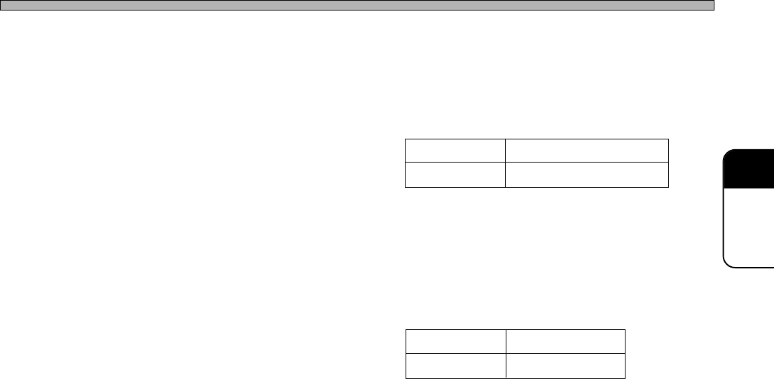
3. OriginOffset
By default, the origin of Coordinates is at the corner of the board. But you can move it by entering
OriginOffset. The range of the value to input in OriginOffset is as follows.
4. BadBoardMarkPos
When using the defective board detecting function, enter the coordinates of the defective board
mark.
5. Mnt End chip Max T
Enter the maximum height of the chip mounted at the previous process so as not to interfere a
nozzle or the chip that is picked up by a nozzle with the mounted chips at during mounting.
- 20 to the board size L
4H4C-E-PMA01-A03-03
Board Data
Input Limits
Input Limits
0 mm to 460 mm
0 mm to 360 mm
X
Y
X
Y
- 20 to the board size W
Page 34
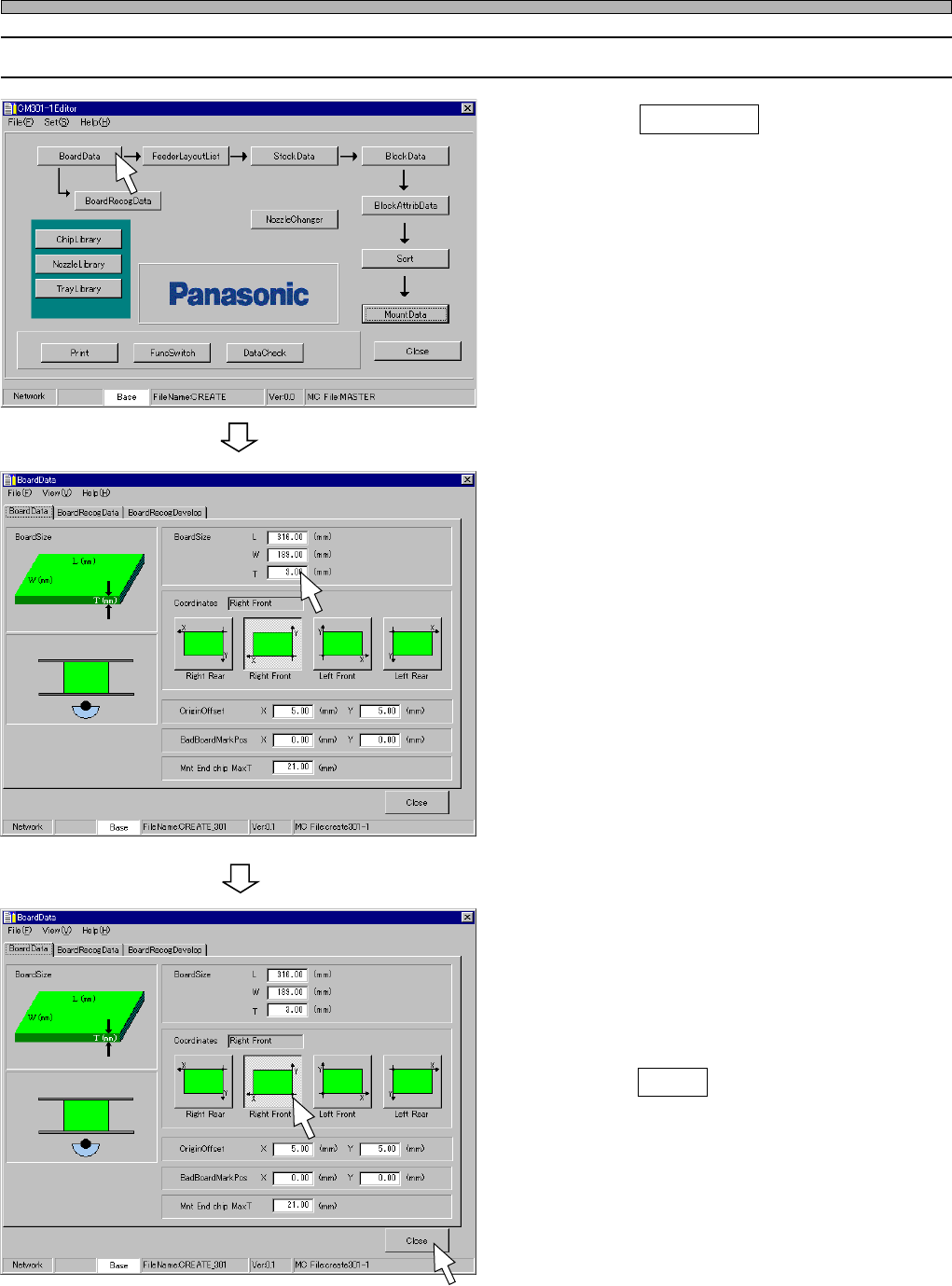
6-2 Editing Board Data
1. Click on BoardData .
• [BoardData] sheet on [BoardData] window
opens.
2. Enter BoardSize.
• Enter the board size L, W, T.
3. Choose Coordinates.
• Enter OriginOffset, if necessary.
4. Click on Close .
• The main menu is displayed.
4H4C-E-PMA01-A03-01
4H4C-EPt-EdBd-002
4H4C-EPt-EdBd-002
Board Data
4H4C-EPt-Ed-001
Page 35
301
CM
4H4C-E-PMA01-A03-01
444C-EPt-EdBr-001
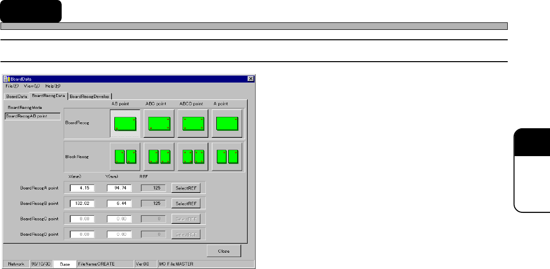
7 Board Recognition Data
7-1 Board Recognition Data
1. BoardRecogMode
2. Board recognition point
∗ Recognition point coordinates (X, Y)
∗ REF
The descriptions are as follows.
∗∗
∗∗
∗ These descriptions are for both board
recognition and block recognition.
1. BoardRecogMode
Choose a mode from the following four according to the number of the points to be recognized.
AB point
This is the most general mode. Mounting position is corrected by recognizing two points on the
board.
Design boards so that the points to be recognized will exist as around the board as possible and
the distance between the two points will be as wide as possible.
ABC point
When you are afraid boards might expand or contract, use this mode. Mounting position is
corrected by recognizing three points on the board. This mode is effective against simple expan-
sion and contraction of L and W.
Design boards so that the points to be recognized will exist as around the board as possible and
the distance among the three points will be as wide as possible.
Compared with AB point, it takes longer time to recognize the board.
ABCD point
When you are afraid boards might expand or contract and they can not be mounted successfully
by using ABC point, use this mode. Mounting position is corrected by recognizing four points on
the board. Depending on the degree of deformity of boards, this mode might not be effective.
Design boards so that the points to be recognized will exist as around the board as possible and
the distance among the four points will be as wide as possible.
It takes the longest time to recognize the board of all the four modes.
A point
Mounting position is corrected by recognizing only one point on the board. So the deviation due
to a rotation in
θ
direction can not be corrected.
It takes the shortest time to recognize the board of all the four modes.