4H4CEPM.pdf - 第58页
Page 48 Stock Data 7. Feeder T able Mode ∗ This can be set only when T able No. 2 is the direct twin feeder (DT40T -40). Specifying the mode for each feeder table can exchange chips according to the state of production. …
Page 47
301
CM
2. Adrs
This shows the position where a feeder will be set.
Table No. 1 has addresses No. 1 to 27. Table No. 2 has addresses L1 to L20 and R1 to R20
(when the optional tray is used). There are 67 addresses in all. (When the optional tray is not used,
there are 47 addresses.)
∗ Table No. 2 can support not only tray feeders but also the feeder table or the manual tray
(option). When the feeder is set, addresses No. 1 to 27 will be made.
3. FeederType
The motion of the machine varies according to the feeder types. Specify the type in this field.
4. PartsName
PartsName registered in the feeder layout list is displayed.
5. ChipName
ChipName registered in the feeder layout list is displayed.
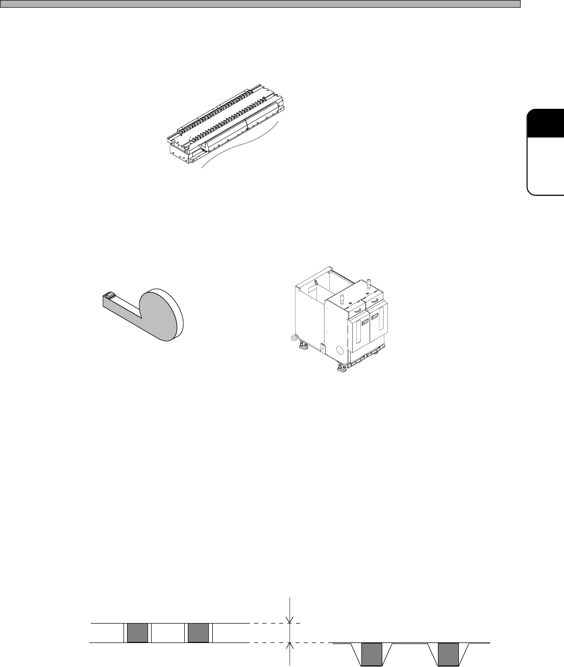
6. Deep (For tape feeders only)
Choose the type of tape that is packing chips.
This data is necessary because the height that chips are picked up varies according to the packing
type of chips.
• Emboss Chips are picked up at the height that they are fed by the feeder.
• Paper Chips are picked up at the height that they are fed by the feeder adding the height of
the chip thickness.
4H4C-E-PMA01-A03-01
Stock Data
1
27
4H4C-604E
Tape Feeder
Tray Feeder
444C-623E
002UC0AA
Paper
Difference of Pickup Height
Emboss
Page 48
Stock Data
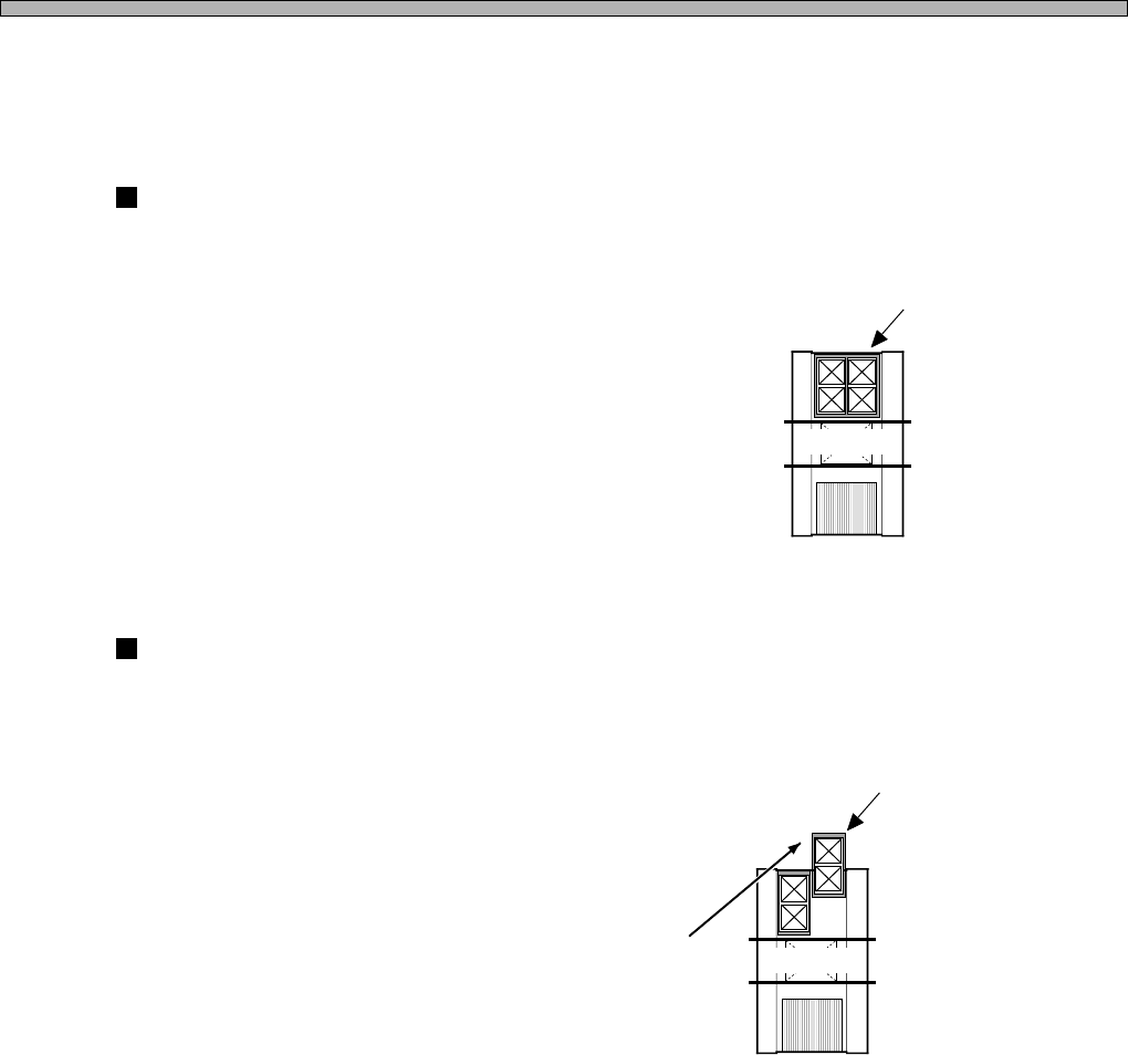
7. Feeder Table Mode
∗ This can be set only when Table No. 2 is the direct twin feeder (DT40T-40).
Specifying the mode for each feeder table can exchange chips according to the state of
production.
JointMode
The feeder table is not divided.
You can not supply chips on the feeder being used but can set a lot of chips of various types.
ReserveMode
Only one of the divided tray feeders is used.
You can draw out the tray feeder that is not used even during production, so you can set the chips
(tray pallets) for the next type of board.
JointMode
4H4C-605E
The reserve tray feeder can be set during production.
4H4C-606E
4H4C-E-PMA01-A03-02
Board A
Board A
ReserveMode
Page 49
301
CM
4H4C-E-PMA01-A03-02
8. Tray Type
The name of the tray that the chips are supplied to is displayed. You can choose the tray from
among the ones input in the custom tray library.
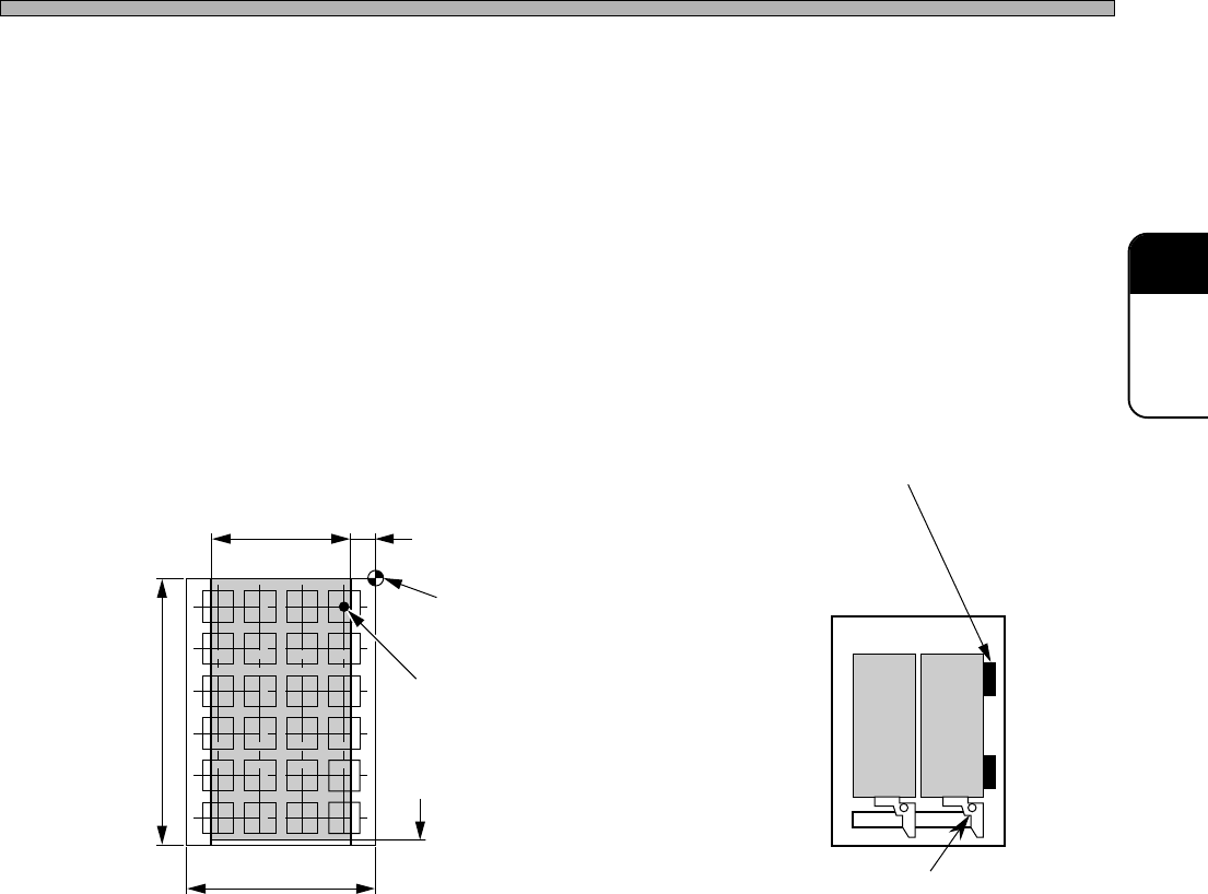
9. Tray Layout
This indicates the position of the tray on the pallet.
Up to two trays can be set on the pallet. To set two trays, the optional clamp (option) is required.
When the distance (in the X direction) between the pick-up point on the tray and the origin is under
12 mm, the pallet offset block (option) is required. To use the offset block for pallet, you need to
input the offset of 8 mm in the tray layout.
Stock Data
Pick-up Possible Range Offset Block for Pallet
Optional ClampTray Max. 230 mm
Tray Setting Reference
(Tray Origin)
Pick-up Position
(Chip Center)
325 mm Pick-up Area
Tray Max. 335 mm
4H4C-616E
4H4C-617E
206 mm 12 mm