HS50_advance_level 1_20200522_221201 (1).pdf - 第105页
Studen t Guide HS-50 A dvanced I 06/200 2 Edition 5 DLM1 C&P Head 13 5.1. 5.2 O vervie w modular he ad board (Opt ion for HS50) Fig. 5.1 - 9 Mod ular head boar d HS 50 (1) Video signals P CB camera (2) Vision I llumi…
06/2002 Edition Student Guide HS-50 Advanced I
5 DLM1 C&P Head
12
5.1.5 Head board
5.1.5.1 Overview Standard head board
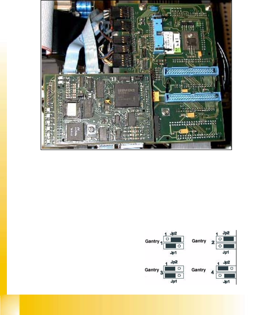
Fig. 5.1 - 8 Standard head board HS50
(1) Video signals PCB camera
(2) Vision Illumination PCB camera
(3) Reference- / Limit switch - Bero‘s
(4) Track signals for X-Axis
(5) Intermediate distributor board for C&P-head
(6) valve drive for placement/pick up position
(7) valve drive reject position
(8) Motor dp-station
(9) Setp motor dp-station
(10) Vacuum test board
(11) LED V9-V14
(12) Jumper Portal 1-4 <=> Kopfplatine
(13) Vision component Camera
(14) Data control LED A0, A1 (see Fig. 5.1 - 12)
1
2
3
4
13
5
5
6
7
8
9
10
11
12
1
2
3
12
1
2
3
12
14
Point 11 LED V9 - V14:
LZOSLight barrier Z-axis upper stop
LZUS Light barrier Z-axis down position
LSOI Light barrier IC Head top position (not used)
LSZD Light barrier Swivel in and turning dp-station
LSVZ Light barrier Vacuum / air blow Z-axis
LSVA Light barrier Vacuum / air blow reject position
Point 12::
Student Guide HS-50 Advanced I 06/2002 Edition
5 DLM1 C&P Head
13
5.1.5.2 Overview modular head board (Option for HS50)
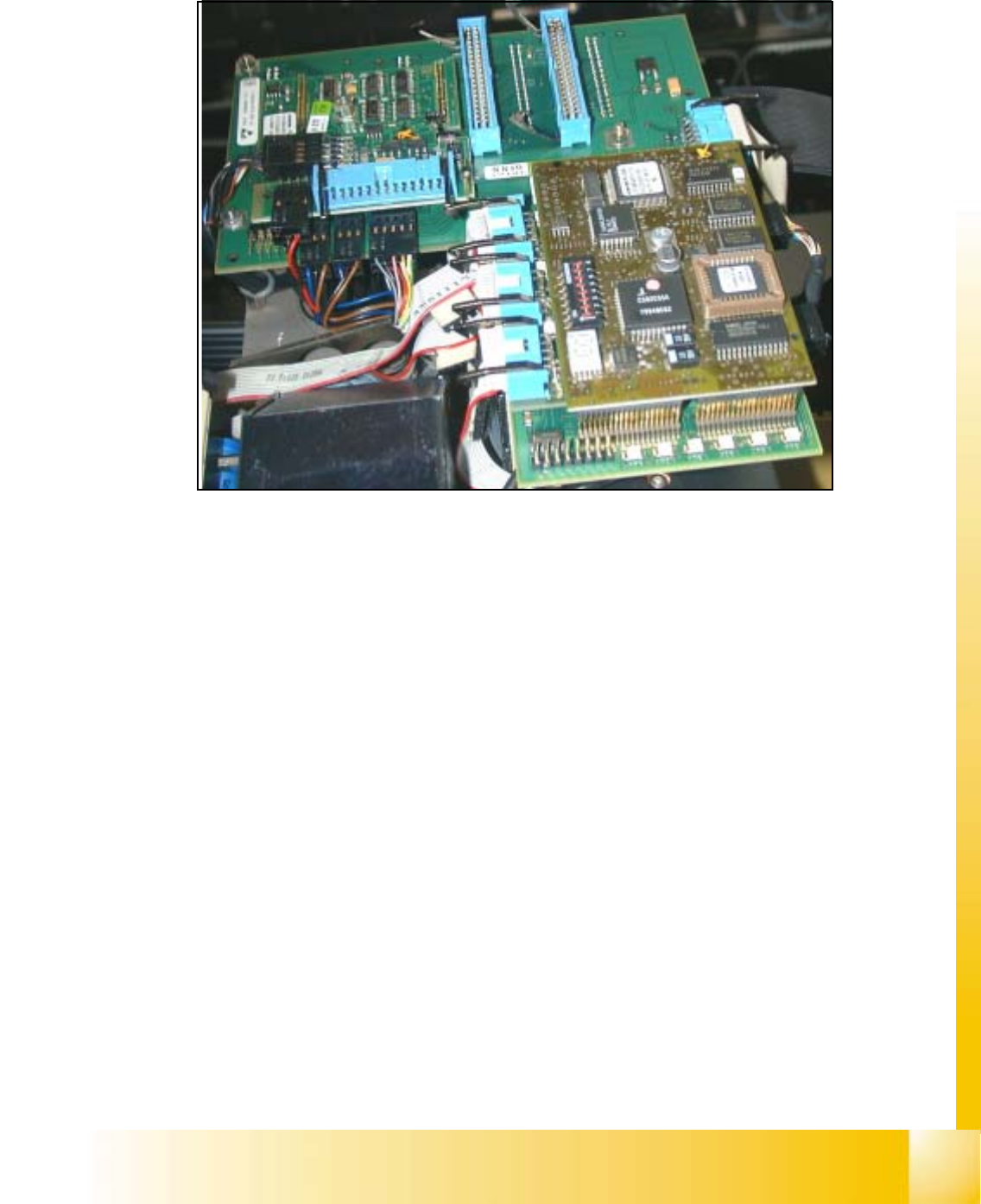
Fig. 5.1 - 9 Modular head board HS50
(1) Video signals PCB camera
(2) Vision Illumination PCB camera
(3) Reference- / Limit switch - Bero‘s
(4) Track signals for X-Axis
(5) Intermediate distributor board for C&P-head
(6) valve drive for placement/pick up position
(7) valve drive reject position
(8) Motor dp-station
(9) Setp motor dp-station
(10) Vacuum test board
(11) LED V9-V14
(12) DIP-Switch Portal 1-4 <=> Kopfplatine
(13) Vision component Camera
(14) 7 Segment display
11
9
8
1
2
3
4
5
5
6
7
13
12
10
14
Point 11 LED V9 - V14:
LZOS Light barrier Z-axis upper stop
LZUS Light barrier Z-axis down position
LSOI Light barrier IC Head top position (not used)
LSZD Light barrier Swivel in and turning dp-sta-
tion
LSVZ Light barrier Vacuum / air blow Z-axis
LSVA Light barrier Vacuum / air blow reject posi-
tion
Point 12: (see Section 5.1.5.3, Page - 14)
Point 14: ( see Fig. 5.1.10, page - 15)
06/2002 Edition Student Guide HS-50 Advanced I
5 DLM1 C&P Head
14
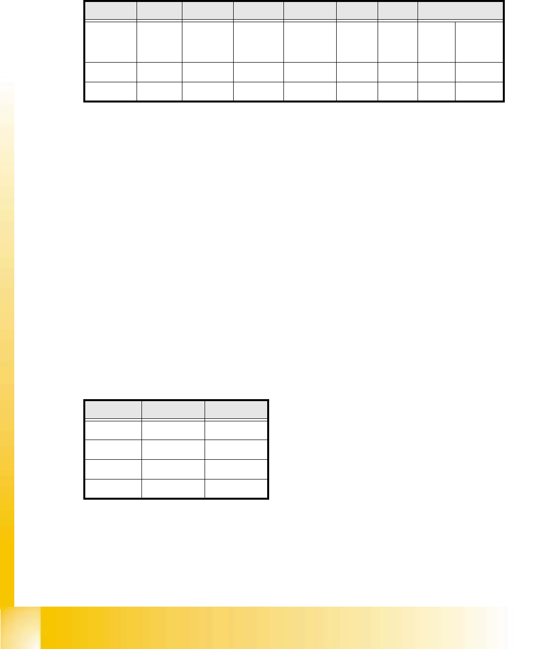
5.1.5.3 New Jumper Setting on the modular head board
Set the DIP switch on the processor board on the basis of the following data.
You will see the position of the switch in Fig. 5.1 - 11 , below.
5
Fig. 5.1.10 Table: DIP Switch
The wiring of the switch depends on the placement machine involved: 5
Jumper 1: ON -> CAN matching resistor on the placement head is set
(S-20, F4, F5), S-23, S-25 HM, F5 HM.
OFF ->CAN_matching resistor is not wired on the head (HS-50 default)
Jumper 2: ON -> Setting during the download
OFF -> Default status
Jumper 3: ON -> Test mode
OFF -> Default status
Jumper 4: ON -> Test mode (setting of CAN ID)
OFF -> Default status
Jumper 5: ON -> Default status
Jumper 6: ON -> Default status
Jumper 7, 8: CAN_ID:
Fig. 5.1 - 11 Table: Gantries CAN_Adress
Standard OFF OFF OFF OFF ON ON CAN_Adress
Position
of switch
1
CAN_R120
2
EPROM_WE
3
Te s t_M o de
4
CAN_ERR_
SWITCH
5
Jumper 5
6
Jumper 6
7
CAN_ID1
8
CAN_ID0
ON X X
OFF X X X X
Gantries Jumper 7 Jumper 8
Gantry 1 ON ON
Gantry 2 ON OFF
Gantry 3 OFF ON
Gantry 4 OFF OFF