HS50_advance_level 1_20200522_221201 (1).pdf - 第73页
Studen t Guide HS-50 A dvanced I 06/200 2 Edition 3 Machi ne Refere nce Run 5 3 Machine Refer ence Run 3.1 Referen ce seque nce in gener al F ig. 3 .1 - 1 R efe ren ce s equ en ce in g en er al 3.2 Prep ara tional ste p …

1 - 4
Contents Student Guide HS-50 Advanced I
06/2002 Edition
4
Student Guide HS-50 Advanced I 06/2002 Edition
3 Machine Reference Run
5
3 Machine Reference Run
3.1 Reference sequence in general
Fig. 3.1 - 1 Reference sequence in general
3.2 Preparational steps
Fig. 3.2 - 1 Preparational steps
50
W
50
W
LC
SC
Next Stations
MC
SIPLACE-LAN
Ø
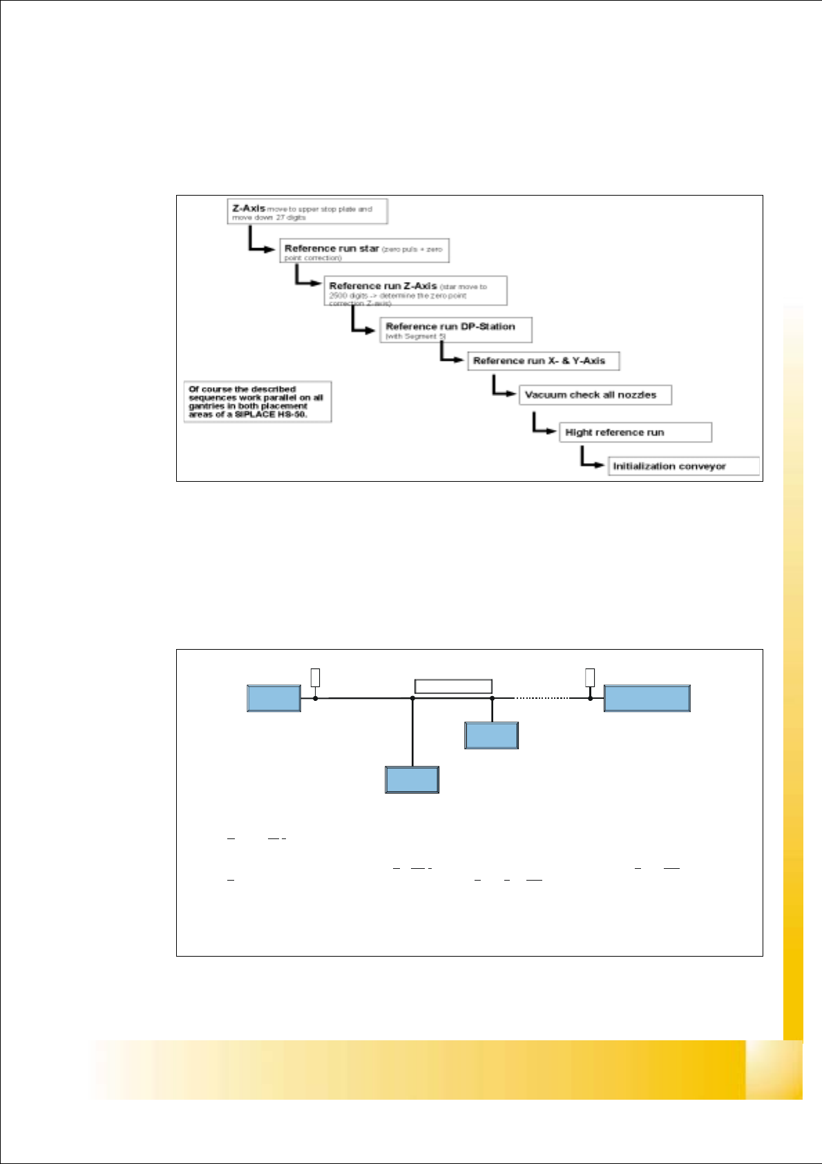
Durin
g
the boot sequence the station sends the first command to the LC, called
S
tation Alife (SALF) command.
Ø
The response of the LC is with LC Alife (LALF) command. It follows with the Load machine
d
ata (LMAD). The data transfer is finished with Load end machine data (LEMA).
Ø
With the start signal the power supply is switched on.
Ø
Pressing the start button starts the reference run.
06/2002 Edition Student Guide HS-50 Advanced I
3 Machine Reference Run
6
3.3 Initialization of the valve drives in pick up / place-
ment and reject position
Fig. 3.3 - 1 Initialization of the valve drives in pick up / placement and reject position
3.4 Initialization of the swivel in / out drive of the
DP_Station
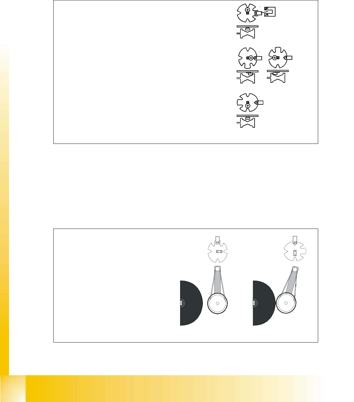
Fig. 3.4 - 1 Initialization of the swivel in / out drive of the DP_Station
Ø
The stepper motor of the valve drive is turned to the
home position.
The stepper motor runs and the light barrier on the
cam disk sets the end signal.
Because of the special shape of the cam disk the
stepper motor is able to recognize the home position
see figure 1.
Ø
Figure 2a. shows position of cam disk when switching
to vacuum.
Ø
Figure 2b. shows position of cam disk when switching
to air kiss.
Ø
During any star movement the excentric is moved off
the valve plunger. This can either be on the home
position or on the oposide position like shown in
figure 3.
1.
2a.
3.
2b.
Ø
The stepper motor of the swivel in / out
drive is turned to the home position.
The stepper motor runs and the light
barrier on the cam disk sets the end
signal.
Because of the special shape of the cam
disk the stepper motor is able to
recognize the home position, seefigure 1.
Ø
Figure 2. Shows the position of the cam
disk when a nozzles is to be moved.
Ø
Diffenrently to the cam disk of the valve
drives here the home position is also the
position when operating the DP servo
1.
2.