HS50_advance_level 1_20200522_221201 (1).pdf - 第55页
Studen t Guide HS-50 A dvanced I 06/200 2 Edition 2 Overview 25 2.9 Secto r 4 Fig. 2.9 - 1 Se ctor 4 Sector 4 c ontai ns the CAN bus a dapter (1) f or the chang eover table of gan try 4, SLIO’s for the safety circuit (2)…
06/2002 Edition Student Guide HS-50 Advanced I
2 Overview
24
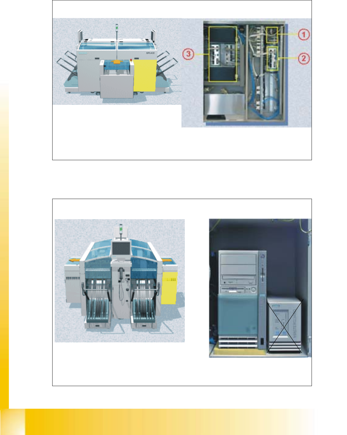
2.7 Sector 1
Fig. 2.7 - 1 Sector1
2.8 Station Computer
Fig. 2.8 - 1 Station computer
PCB input side Sector 1
Sector 1 contains CAN bus adapter (1) for the changeover table of gantry 1, an additional SLIO
for the optional nozzle changers (2), and the conveyor control unit (3)
One of the main funktions of the station computer is to
provide a graphical user interface for operating the ma-
chine. It also acts as a communication interface between the Line computer and the machine
controller
Left view (main operator controls) Station computer
Student Guide HS-50 Advanced I 06/2002 Edition
2 Overview
25
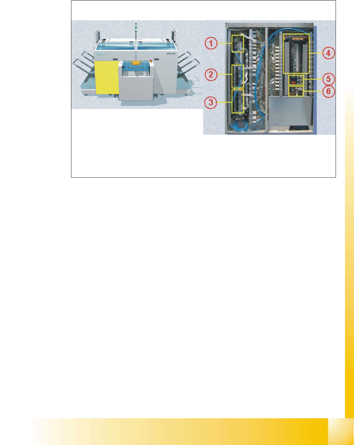
2.9 Sector 4
Fig. 2.9 - 1 Sector 4
Sector 4 contains the CAN bus adapter (1) for the changeover table of gantry 4, SLIO’s for the
safety circuit (2) and the first nozzle changer (3) among others, the main distributor (4), the
power supply unit for the step motors (5), and the illumination and flash distributor(6).
PCB input side Sector 4
06/2002 Edition Student Guide HS-50 Advanced I
2 Overview
26
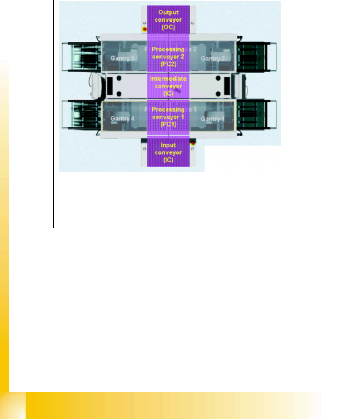
2.10 PCB Transport
2.10.1 Tranport set up
Fig. 2.10 - 1 Transport system
The HS-50 is divided into two processing areas:
- Processing Area 1 with gantries 1 and 4
- Processing Area 2 with gantries 2 and 3
The conveyor belt is also divided into a number of sections
– Input conveyor belt
– Processing conveyor belt 1
– Intermediate conveyor belt
– Processing conveyor belt 2
– Output conveyor belt