HS50_advance_level 1_20200522_221201 (1).pdf - 第558页
Studen t Guide HS-50 A dvanced I 06/200 2 Edition 20 App endix 31 20. 4.5. 4 V a cuum ch eck “ seg men t seal ed” b efo re p ick up Fig. 20.4 - 6 Vacu um che ck “segme nt seal ed” bef ore pi ck up 1. T he quality of t he…
06/2002 Edition Student Guide HS-50 Advanced I
20 Appendix
30
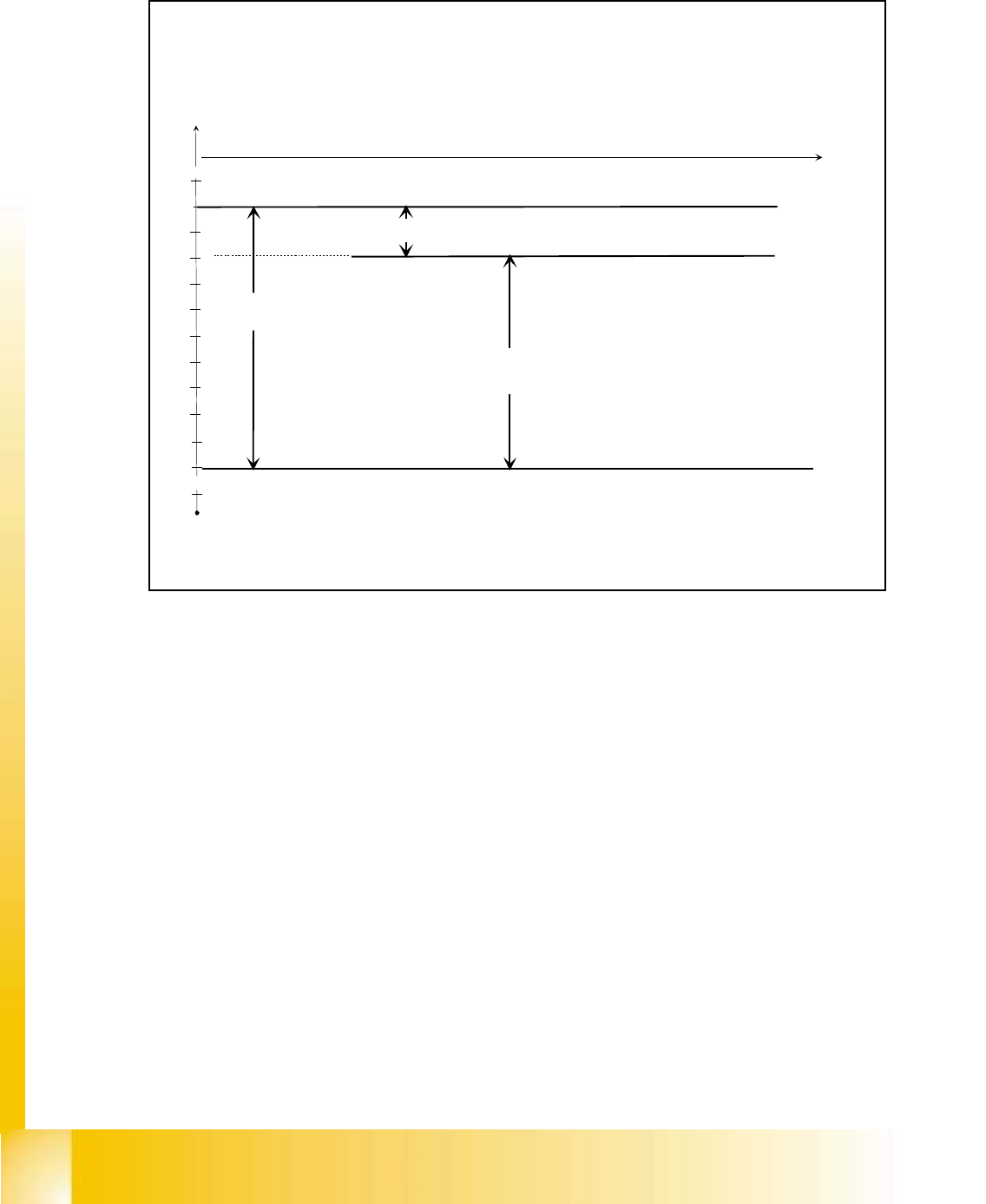
20.4.5.3 Vacuum check before placement
Fig. 20.4 - 5 Vacuum check before placement
1. Another vacuum check is made before placement, this ensures the component is still at the
nozzle.
2. The same threshold values apply as during pick up. Any failed components will be rejected dur-
ing the next pick up cycle.
-700
-720
-740
-760
-780
-800
-820
-840
-860
-880
-900
0
t
maximum vacuum
Vacuum nozzle closed
Vacuum nozzle open
Vacuum difference at
the last reference run
Environment pressure
Component is rejected at reject box at the next pick up cycle
Component is accepted
at vacuum check
20%
Pressure difference nozzle - inside -> environment
Student Guide HS-50 Advanced I 06/2002 Edition
20 Appendix
31
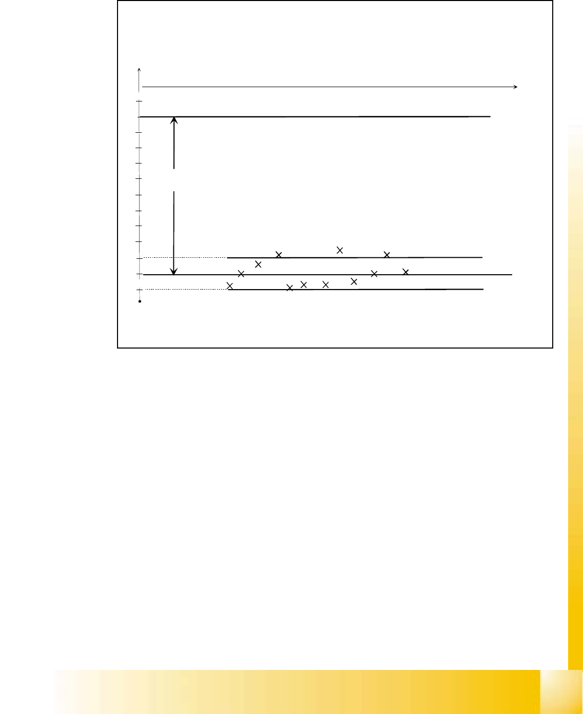
20.4.5.4 Vacuum check “segment sealed” before pick up
Fig. 20.4 - 6 Vacuum check “segment sealed” before pick up
1. The quality of the segment seal is checked prior to each pick up.
2. This tests the quality of the seal given by the vacuum pluneer.
3. Normally the result should be within ± 20 mbar of the closed result determined during refer-
ence.
4. If a result is outside the tolerance, then the machine logs an error. If the error occurs 3 times
within 350 placements at the same segment, an error is reported "Leaky segment".
5. If this error occurs check the condition of the value plunger.
6. The values for 20 mbar, 3 errors and 350 placements are in the vacuum.MA file.
-700
-720
-740
-760
-780
-800
-820
-840
-860
-880
-900
0
t
-920
Threshold -20 mbar
Threshold +20 mbar
Vacuum difference
at reference run
1.Error on this
segment is logged
2. Error logged
3. Error on this
segment is displayed
Pressure difference nozzle - inside -> environment

06/2002 Edition Student Guide HS-50 Advanced I
20 Appendix
32
20.4.5.5 Air kiss at placement or at reject position
Fig. 20.4 - 7 Air kiss at placement or at reject position
1. Air kiss is applied at placement and reject positions to remove the component from the nozzle.
2. The placement pressure should be set to:
0.15 bar 71x/91x nozzles
0.20 bar 70x/90x nozzles 20
3. The reject pressure should be set to 0.25 bar.
200
160
120
80
40
0
t
240
Air kiss at placement position to
remove the vacuum in the nozzle
and to place the component
Air kiss at reject position to remove the vacuum
in the nozzle and to reject the component.
Pressure difference nozzle - inside -> environment