HS50_advance_level 1_20200522_221201 (1).pdf - 第497页
06/2002 E dition S tudent Guide HS-50 Advance d I 12 Preve ntive Maintenance 64

Student Guide HS-50 Advanced I 06/2002 Edition
12 Preventive Maintenance
63
You will need the following tools, consumables and spare parts for the annual maintenance:
– Grease cartridge (item no. 02101696-01)
– SIPLACE cleaning cloth (item no. 00315253-01)
– ISOFLEX TOPAS NCA52 (Item no. 00328369-01can 1kg, 8-pack: 00366831-01)
– Damping tube protective cover (item no. 00334359-01).
: Select "Disable interface" on the station computer. The placement system will continue until
the last PCB is complete and has left the PCB conveyor.
: Open the two protective covers on one side of the machine (gantries 1+4 or 2+3).
: Move the gantry over the feeder modules. This will leave your working area clear.
12
Take hold of the handle and carefully move the gantry. Do not use too much force.
Clean and protect the PCB conveyor
a Clean and protect the recirculating ball screw by wiping a SIPLACE cleaning cloth over the
threads of the recirculating ball screw.
s Clean and grease the sliding surfaces of the guide rails with a SIPLACE cleaning cloth.
: Clean and protect the hexagonal shafts with a SIPLACE cleaning cloth.
: Clean and protect the guide shafts of the PCB stopper with a SIPLACE cleaning cloth.
06/2002 Edition Student Guide HS-50 Advanced I
12 Preventive Maintenance
64

Student Guide HS-50 Advanced I 06/2002 Edition
12 Preventive Maintenance
65
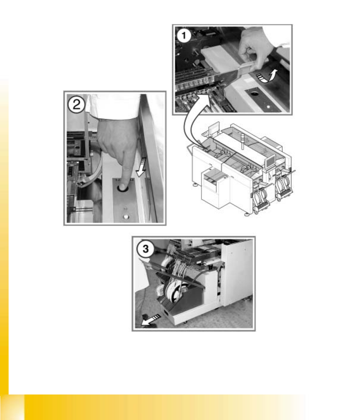
Maintaining the empty tape cutter
Dismantling the component change-over table:
WARNING
Always couple the component change-over table to the machine before connecting or disconnect-
ing the component change-over table power cable at the machine socket.
: Move the gantry over the placement area. This will stop it outside your working area.
12
To move the gantry, take hold of the handle and push gently and carefully.
a Open the safety flap on the component table.
s Press the valve for the component change-over table lifting mechanism.
Hold it down until the component table reaches its top end position.
: Disconnect the component change-over table power cable from the placement machine.
d Pull the component change-over table out of the machine.
: Detach the waste tape chute.
: Check the cutting surfaces of the cutting blades.
The cutting blade must be turned if any irregularities are identified on the cutting surfaces. If
the cutting blade has already been turned, then it must be replaced with a new blade.
Please contact the SIPLACE Service.
: Reverse the order described above to fit the waste tape chute and component table.
: Select “Block manually” (status open) on the station computer and click on OK (for dual con-
veyor track 1 / track 2).
: Repeat these tasks at every placement machine on the line.
: Switch the placement system on again at the main switch.
: Repeat these tasks on both sides of the machines on the placement line.