HS50_advance_level 1_20200522_221201 (1).pdf - 第201页
Studen t Guide HS-50 A dvanced I 06/200 2 Edition 6 Operat ing the S ITE ST S o ftware 17 Cal l-up of th e ga nt ry fu ncti ons. Call- u p of th e d ispl ay o f the gant ry ax is f un ct ions . Call- u p of th e d ispl a…
06/2002 Edition Student Guide HS-50 Advanced I
6 Operating the SITEST Software
16
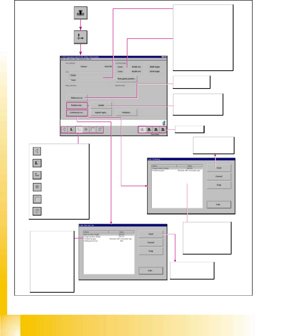
6.4.2 Gantry Axis Functions
Call-up of the gantry functions.
Call-up of the display of the
gantry axis functions.
Call-up of the display of the
gantry's calibration functions.
Call-up of the display of the
gantry's PCB mapping
functions.
Call-up of the display of the
gantry's PCB camera
functions.
Return to the main view.
Axis
X-axis
Activates the functions for adjusting the X-
axis.
Y-axis
Activates the functions for adjusting the Y-
axis.
Current position (of the activated axis)
X-pos.
Indicates the current x-position of the axis.
Y-pos.
Indicates the current y-position of the axis.
Read gantry position
The current gantry position is displayed
continuously.
Update
Updates the actual position of the
selected axis and displays the x- and
y-positions of the axis in the Current
position work area.
Start
The axis starts the continuous
run with the specified target
position and positioning type.
Target position [digits]
Enter the desired target position
for the selected axis.
Positioning type
Defines the method to be used
for positioning the axis.
Reference run
Carries out a reference
run of the activated axis.
Selects gantry 1-4.
Start
The axis travels in a continuous
run between the start and target
positions entered.
Start position [digits]
Enter the desired start position
for the selected axis.
Target position [digits]
Enter the desired target
position for the selected axis.
Positioning type
Defines the method to be used
for positioning the axis.
Waiting time [msec]
Indicates the length of time the
axis is to remain in the start
and/or target position during
the continuous run.
Student Guide HS-50 Advanced I 06/2002 Edition
6 Operating the SITEST Software
17
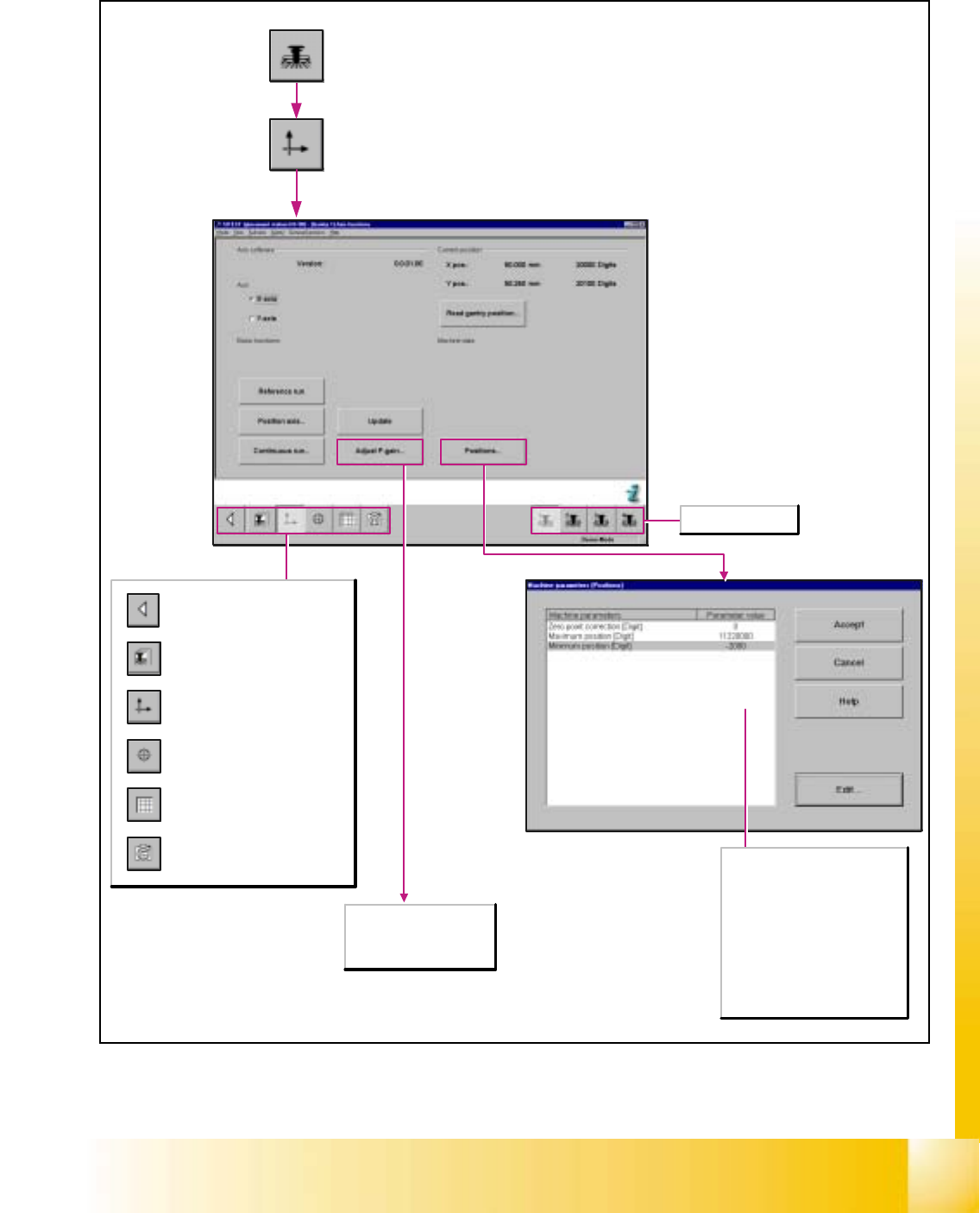
Call-up of the gantry functions.
Call-up of the display of the
gantry axis functions.
Call-up of the display of the
gantry's calibration functions.
Call-up of the display of the
gantry's PCB mapping
functions.
Call-up of the display of the
gantry's PCB camera
functions.
Return to the main view.
Zero point corrections [digit]
Corrects the reference point by
the preset value.
Maximum position [digit]
Indicates the maximum
attainable position of the axis.
Minimum position [digit]
Indicates the minimum
attainable position of the axis.
Selects gantry 1-4.
Any tacho adjustment for
the x- and y-axes of the
SIPLACE HS-50 / HS-55
is not possible.
06/2002 Edition Student Guide HS-50 Advanced I
6 Operating the SITEST Software
18
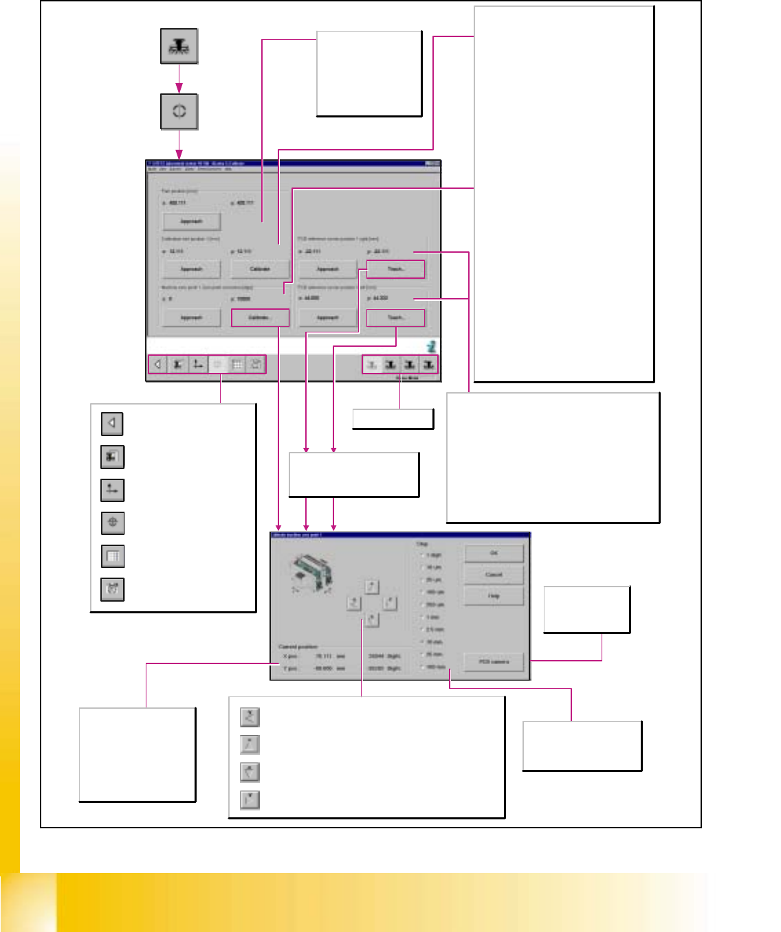
6.4.3 Gantry‘s Calibration Functions
Upon each actuation of the button, the active gantry is advanced by
one increment of the selected step size in positive y-direction.
Upon each actuation of the button, the active gantry is advanced by
one increment of the selected step size in positive x-direction.
Upon each actuation of the button, the active gantry is advanced by
one increment of the selected step size in negative x-direction.
Upon each actuation of the button, the active gantry is advanced by
one increment of the selected step size in negative y-direction.
Call-up of the gantry functions.
Call-up of the display of the
gantry axis functions.
Call-up of the display of the
gantry's calibration functions.
Call-up of the display of the
gantry's PCB mapping
functions.
Call-up of the display of the
gantry's PCB camera
functions.
Return to the main view.
Park position [mm]
X/Y
Indicates the x/y-position
of the gantry's park
position.
Approach
Moves the gantry to the
Park position.
Calibration tool position 1 [mm]
X/Y
Indicates the calibration tool's x/y-position
determined by calibration as well as the previous
x-position (in parentheses).
Approach
Moves the gantry with the PCB camera mounted
to it over the calibration tool position and
switches the screen display to the PCB camera
for verification purposes. The calibration tool
must be visible in the camera's field of view.
Calibrate
Determines the x and y-positions of the
calibration tool.
Machine zero point: Zero Point Correction
[Digit]
X/Y
Indicates the zero point correction determined
by calibration as well as the previous zero point
correction (in parentheses) in x/y-direction.
Approach
Moves the gantry with the PCB camera mounted
to it over the measuring hole for the machine
zero point and switches the screen display to the
PCB camera for verification purposes. The
machine zero point must be visible in the
camera's field of view.
Calibrate
Opens the Teach dialog window for approaching
the position of the machine zero point.
Subsequently, the zero point correction of the x-
and y-axes is determined within the scope of the
calibration procedure.
Step
The desired step size for
traversing the gantry can be
activated in a given resolution.
PCB camera
Switches the
screen display to
the PCB camera.
Selects gantry 1-4.
PCB reference corner position 1 right/left [mm]
X/Y
Indicates the x/y-position of the PCB reference corner
determined during teaching as well as the previous x-
position of the PCB reference corner (in parentheses).
Approach
Checks the position of the PCB reference corner
right.Moves the active gantry with the PCB camera
mounted to it over the PCB reference corner and
switches the screen display to the PCB camera for
verification purposes.The position of the PCB reference
corner must be visible in the camera's field of view.
X-pos.
Indicates the applicable
gantry's x-position
approached during teaching.
Y-pos.
Indicates the applicable
gantry's y-position
approached during teaching.
The Teach function for PCB
reference corners is not available
in the long PCB with additional
stopper transport mode.