HS50_advance_level 1_20200522_221201 (1).pdf - 第172页
06/2002 E dition Studen t Guide H S-50 Advance d I 5 DLM1 C&P H ead 80 5 F ig. 5. 4 - 34 Lay in g th e ri bb on c ab les fo r th e va lve a d just me nt drive s

Student Guide HS-50 Advanced I 06/2002 Edition
5 DLM1 C&P Head
79
CAUTION 5
Check that the ribbon cables (item 1 and 2 in Fig. 5.4 - 11
) are laid correctly. The ribbon cable
(item 2 in Fig. 5.4 - 11
) from the valve adjustment unit to the reject station (item 6 in Fig. 5.4
- 11) must run outside the hole (item 5 in Fig. 5.4 - 11), otherwise it will be damaged when the
collect&place head is fitted on the head mount. 5
5
5
5
5
5
5
5
5
5
5
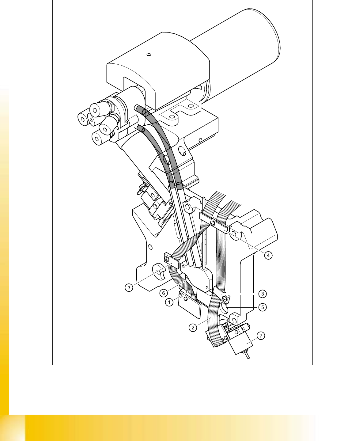
Key to Fig. 5.4 - 11
(1) Flat ribbon cable for the ’Placement’ valve adjustment unit
(2) Flat ribbon cable for the ’Reject circuit’ valve adjustment unit
(3) Cable clamp assembly
(4) Cable clamp assembly
(5) Hole
(6) ’Placement’ valve positioning drive
(7) ’Reject circuit’ valve positioning drive
5
06/2002 Edition Student Guide HS-50 Advanced I
5 DLM1 C&P Head
80
5
Fig. 5.4 - 34 Laying the ribbon cables for the valve adjustment drives
Student Guide HS-50 Advanced I 06/2002 Edition
5 DLM1 C&P Head
81
5.4.14.5 Mechanical adjustment
5
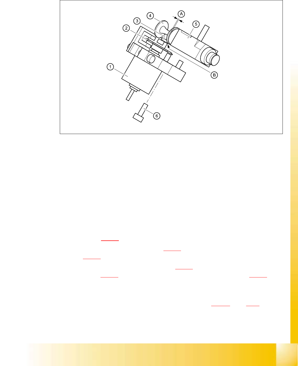
Fig. 5.4 - 35 Mechanical adjustment of the valve positioning drives
(1) Stepping motor
(2) Adjusting disk
(3) Deep-groove ball bearings
(4) Valve plunger
(5) Valve casing
(6) M3x10 hexagon socket-head screw
(7) Valve positioning drive (flange)
5
➠ Use the feeler gauge to set the distance between the valve plunger and valve casing to 0.2 mm
(item A in Fig. 5.4 - 12
).
➠ Turn the adjusting disk (see item 2 in Fig. 5.4 - 12) until the deep-groove ball bearings (item 3
in Fig. 5.4 - 12
) point towards the valve casing.
➠ Move the valve positioning drive (item 7 in Fig. 5.4 - 12) so that the deep-groove ball bearings
(item 3 in Fig. 5.4 - 12
) come into contact with the valve plunger (item 4 in Fig. 5.4 - 12) at
position B.
➠ Use the hexagon socket-head screw (item 6) to fix valve adjustment unit in this position.
➠ Attach the collect&place head to the head mount (see section 5.4.12.4, page 5 - 72).