HS50_advance_level 1_20200522_221201 (1).pdf - 第59页
Studen t Guide HS-50 A dvanced I 06/200 2 Edition 2 Overview 29 F ig. 2.1 1 - 2 Cha ng eove r t able , conn ec to r 2.1 2 Gantr y 2.12.1 Gantries an d place m ent ar eas Fig. 2.12 - 1 Gan tri es and place ment areas Powe…
06/2002 Edition Student Guide HS-50 Advanced I
2 Overview
28
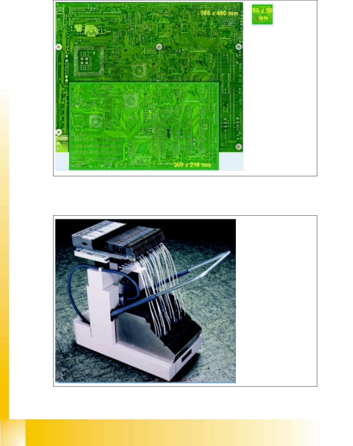
2.10.3 Board Sizes
Fig. 2.10 - 4 PCB sizes
2.11 Component Changeover Table
Fig. 2.11 - 1 Component changeover table
The conveyor can be
used to transport PCBs
with a surface area or
between 50X50 mm
and 368X460 mm
(or 368X216 mm in the
case of a dual conveyor)
and a thickness
between
0,3 mm and 4,5 mm
The changeover tables are
equipped with rollersand a
pneumatic lifting table for
the component feeder table.
This eliminates the need for
a second lifting table for re-
moval and replacement.
Each table has twelfe slots
for 8 mm SIPLACE feeders.
Given that each feeder has
two 8mm tracks the HS-50
has a total capacity of 98
tracks for 8mm tapes
Student Guide HS-50 Advanced I 06/2002 Edition
2 Overview
29
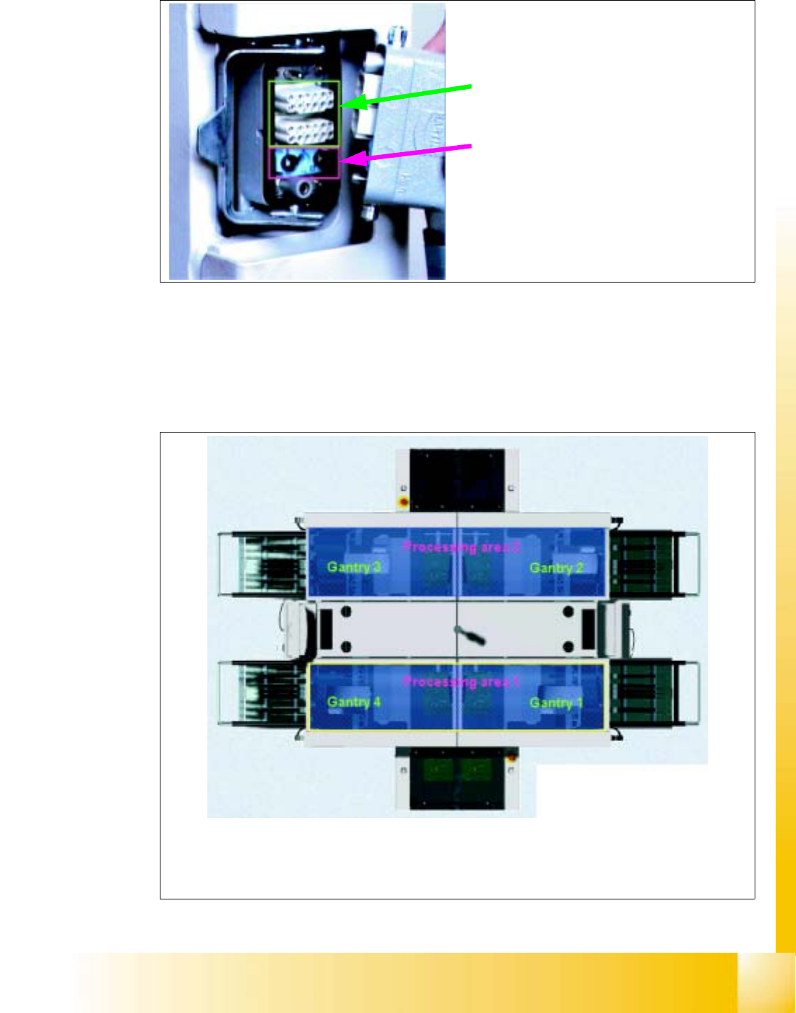
Fig. 2.11 - 2 Changeover table, connector
2.12 Gantry
2.12.1 Gantries and placement areas
Fig. 2.12 - 1 Gantries and placement areas
Power, control signals
and
compressed air
are supplied via a shared plug connection
The HS-50 is divided into two processing areas:
Processing area 1 with gantries 1 and 4
Processing area 2 with gantries 2 and 3
06/2002 Edition Student Guide HS-50 Advanced I
2 Overview
30
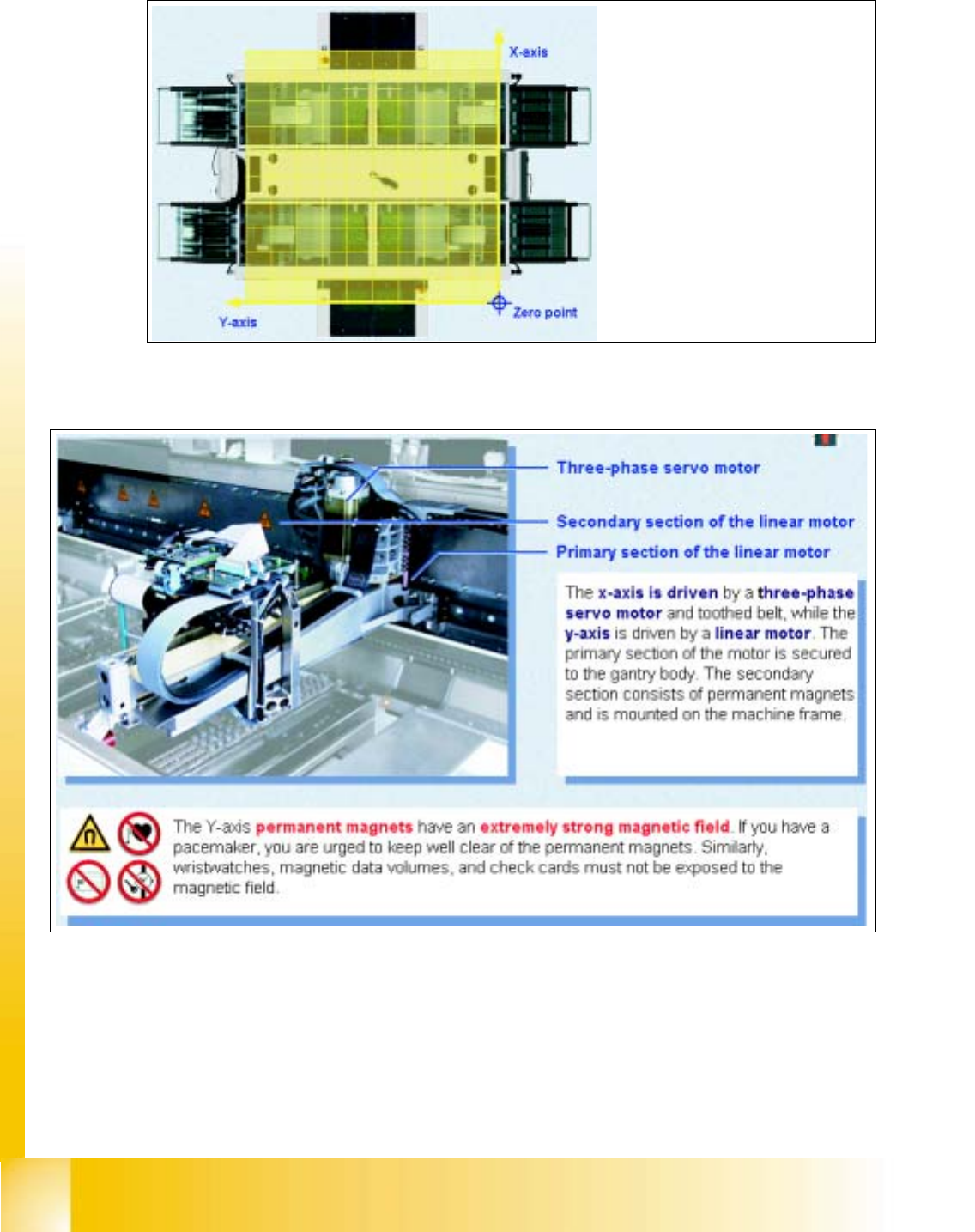
2.12.2 Coordinate System
Fig. 2.12 - 2 Coordinate system
2.12.3 The HS-50 is a four gantry machine with AC drives
Fig. 2.12 - 3 The Y- and X-axes
The zero point of the coordinate
system is located outside the ma-
chine in order to avoid negative
coordinates