HS50_advance_level 1_20200522_221201 (1).pdf - 第109页
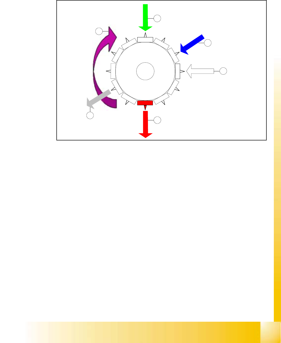
Studen t Guide HS-50 A dvanced I 06/200 2 Edition 5 DLM1 C&P Head 17 5.2. 2 Wo rking positi on s at the placement head Fig. 5.2 - 1 Wo rkin g posit ions at th e plac ement head Key (1) Optical centering (2) turning s…

06/2002 Edition Student Guide HS-50 Advanced I
5 DLM1 C&P Head
16
5.2 Pick up Cycle of the C&P-Head
5.2.1 Steps when picking up and placing components
– A PCB moves into the placement area of the PCB conveyor.
– The right-hand revolver head picks up components from the feeder modules.
– The left-hand revolver head waits for the fiducial measurement.
– Once the fiducial measurement is complete, the right-hand revolver head places components
while the left-hand revolver head picks up further components.
– The right-hand revolver head picks up components, and so on.
5.2.1.1 Position and function of the individual star stations (see Fig. 5.1 - 5)
Star station 1 5
Pick-up cycle 5
The nozzle is lowered onto the component. Once the valve positioning unit has opened the vac-
uum circuit to the nozzle, the nozzle draws up the component and removes it from the feeder mod-
ule. 5
Star station 3 5
The valve positioning unit closes the vacuum channel to the nozzle. Defective components are
detached from the nozzle with a short burst of compressed air and are discarded. 5
Star station 7 5
The component is optically centered. 5
Star station 9 5
Pick-up cycle 5
The nozzle is rotated to the pick-up position. 5
5
5
5
Student Guide HS-50 Advanced I 06/2002 Edition
5 DLM1 C&P Head
17
5.2.2 Working positions at the placement head
Fig. 5.2 - 1 Working positions at the placement head
Key
(1) Optical centering
(2) turning station
(3) service position for segment removal of the sleeve
(4) pick up / placement station
(5) reject position
(6) working direction
1
2
1
1
1
0
9
8
7
6
5
1
2
3
4
1
2
3
4
5
6
06/2002 Edition Student Guide HS-50 Advanced I
5 DLM1 C&P Head
18
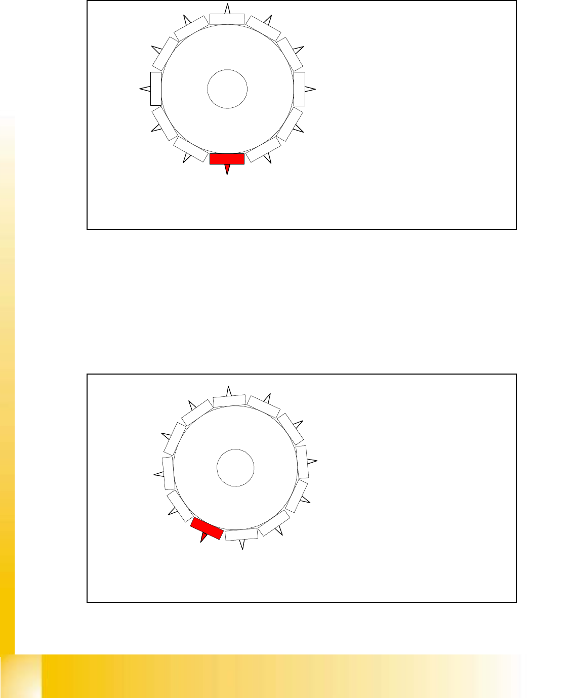
5.2.3 12 nozzle Collect & Place head in home position
Fig. 5.2 - 2 12 nozzle Collect & Place head in home position SR/MC 407.XX
This is the home position of the 12 nozzle Collect & Place head.
When the X- and Y-axis is in waiting position the star-axis is turned to home position.
5.2.4 12 nozzle Collect & Place head in home position 15
°
Fig. 5.2 - 3 12 nozzle Collect & Place head in home position SR/MC 502.XX
Star position
Digit: 00.000
Angle: 0 °
1
2
1
1
1
0
9
8
7
6
5
1
2
3
4
When the X- and Y-axis is in waiting position
the Star-axis is turned to home position
1
2
1
1
1
0
9
8
7
6
5
1
2
3
4
the Star-axis is turned to home position.
Star position
Digit: 05.900
Angle: 15
o
When the X- and Y-axis is in waiting position
For SW version 407 / 502 home position is at 15
o