HS50_advance_level 1_20200522_221201 (1).pdf - 第538页
Studen t Guide HS-50 A dvanced I 06/200 2 Edition 20 App endix 11 20.3.8 Gauge for Z- Axis 20 fig 20. 3 - 10 Gauge f or st ar 00 3313 08-01 Applica tion: 20 The gauge is used for the adjustment of the z-axis stop on the …
06/2002 Edition Student Guide HS-50 Advanced I
20 Appendix
10
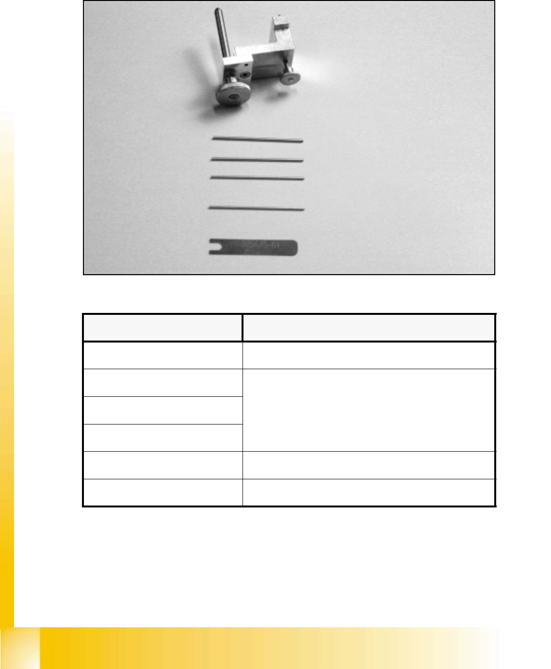
20.3.7 Calibration Tool for the Collect & Place Head
20
fig 20.3 - 9 Calibration tool for the Collect & Place Head 10.000, item number: 00327005-01
20
Gauge for the star, item no: 00326164-01
Parallel pin 1.4 mm, item no: 00326160-01
Parallel pin 1.5 mm, item no: 00326161-01
Parallel pin 1.6 mm, item no: 00326162-01
Parallel pin 1.3 mm item no: 00326163-01
Distance gauge, item no: 00325445-01
Measuring tools Usage
Gauge for the star Adjustment of zero point correction star
Parallel pin 1.4 mm
Adjustment of distance between read head of dp - station to glass
pane of sleeve
Parallel pin 1.5 mm
Parallel pin 1.6 mm
Parallel pin 1.3 mm Adjustment of distance light barrier z-axis bottom to sleeve
Distance gauge Adjustment of the distance between valve plunge and star
Student Guide HS-50 Advanced I 06/2002 Edition
20 Appendix
11
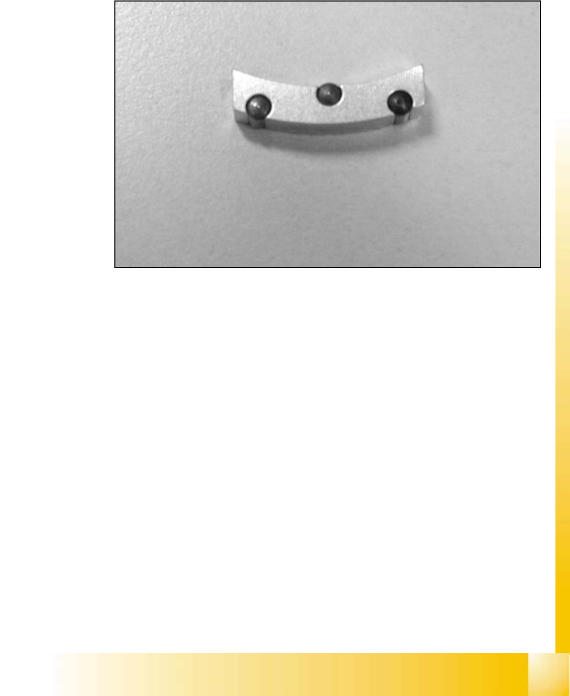
20.3.8 Gauge for Z-Axis
20
fig 20.3 - 10 Gauge for star 00331308-01
Application: 20
The gauge is used for the adjustment of the z-axis stop on the top. 20

06/2002 Edition Student Guide HS-50 Advanced I
20 Appendix
12
20.4 Assessment of machine status
20.4.1 Check list to start machine trouble shooting
The following list is designed to offer a logical method of assessing the condition of a machine to
enable troubleshooting to begin. The idea is to follow a set pattern to avoid missing basic problems
with the machine before more in depth troubleshooting begins.
1. Visual inspection of the machine.
– Check the head and gantry for freedom of movement. Take care that the Z-axes of the C&P
head are not in the down position before moving the gantry manually.
– Make sure the feeders are set correctly on the feeder tables. The feeders should be seated
firmly without sitting on any components. All feeder flaps should be properly closed.
– Inspect all Feeder tables for proper cable connections.
– Make sure the Dummy plug is properly installed.
– Ensure that no tools or materials are obstructing the path of the gantry that may cause a
head crash.
2. Turn on the machine.
– Ensure the line computer is booted up properly.
– Switch on the station.
3. Begin the preliminary walk-around of the machine.
– Check the LED’s on the ICOS vision card.
– Check the LED’s on machine controller for any fault indications.
– Check the LED’s on the power supply, (for S23 and new generation machines.)
– Check the LED’s on the axes boards for any fault indications.
– Check the LED’s on servo cage for any fault indications.
– Check the LED’s on machine head for proper communication signaling.
– Make sure the incoming Air pressure gauge indicates the proper operational pressure
range.
4. Check the Graphical User Interface (GUI) for proper operation.
– Check for the completion of the software booting sequence.
– Monitor the screen for any errors.
– Press the Start key to initiate the reference run when prompted to.