HS50_advance_level 1_20200522_221201 (1).pdf - 第96页
1 - 4 06/2002 E dition Studen t Guide H S-50 Advance d I Cont ents 4 5.4 C& P Head dis- and reassem bly . . . . . . . . . . . . . . . . . . . . . . . . . . . . . . . . . . . . . . . . . . . . . . . . . . . 32 5.4. 1 …

Page
Contents 0
Student Guide HS-50 Advanced I 06/2002 Edition
Contents
3
5 DLM1 C&P Head . . . . . . . . . . . . . . . . . . . . . . . . . . . . . . . . . . . . . . . . . . . . . . . . . . . . 5
5.1 General Overview. . . . . . . . . . . . . . . . . . . . . . . . . . . . . . . . . . . . . . . . . . . . . . . . . . . . . . . . . . . . . . . . 5
5.1.1 Overview . . . . . . . . . . . . . . . . . . . . . . . . . . . . . . . . . . . . . . . . . . . . . . . . . . . . . . . . . . . 5
5.1.2 Parts overview. . . . . . . . . . . . . . . . . . . . . . . . . . . . . . . . . . . . . . . . . . . . . . . . . . . . . . . 6
5.1.3 Overview of the functions of star stations 1 - 12 . . . . . . . . . . . . . . . . . . . . . . . . . . . . . 9
5.1.4 Overview about the structure vacuum and air kiss . . . . . . . . . . . . . . . . . . . . . . . . . . 10
5.1.5 Head board . . . . . . . . . . . . . . . . . . . . . . . . . . . . . . . . . . . . . . . . . . . . . . . . . . . . . . . . 12
5.2 Pick up Cycle of the C&P-Head . . . . . . . . . . . . . . . . . . . . . . . . . . . . . . . . . . . . . . . . . . . . . . . . . . . 16
5.2.1 Steps when picking up and placing components. . . . . . . . . . . . . . . . . . . . . . . . . . . . 16
5.2.2 Working positions at the placement head . . . . . . . . . . . . . . . . . . . . . . . . . . . . . . . . . 17
5.2.3 12 nozzle Collect & Place head in home position . . . . . . . . . . . . . . . . . . . . . . . . . . . 18
5.2.4 12 nozzle Collect & Place head in home position 15°. . . . . . . . . . . . . . . . . . . . . . . . 18
5.2.5 Turn nozzle 1 to Pick up angle (0° or 90°). . . . . . . . . . . . . . . . . . . . . . . . . . . . . . . . . 19
5.2.6 Pick up first Component . . . . . . . . . . . . . . . . . . . . . . . . . . . . . . . . . . . . . . . . . . . . . . 20
5.2.7 Pick up 6th component . . . . . . . . . . . . . . . . . . . . . . . . . . . . . . . . . . . . . . . . . . . . . . . 21
5.2.8 Pick up 7th component . . . . . . . . . . . . . . . . . . . . . . . . . . . . . . . . . . . . . . . . . . . . . . . 22
5.2.9 PCB position recognition run to the PCB nominal position . . . . . . . . . . . . . . . . . . . . 23
5.2.10 Pick up 8th component . . . . . . . . . . . . . . . . . . . . . . . . . . . . . . . . . . . . . . . . . . . . . . 23
5.2.11 Pick up 9th Component. . . . . . . . . . . . . . . . . . . . . . . . . . . . . . . . . . . . . . . . . . . . . . 24
5.2.12 Pick up 12th component . . . . . . . . . . . . . . . . . . . . . . . . . . . . . . . . . . . . . . . . . . . . . 25
5.3 Placement Cycle of the C&P-Head. . . . . . . . . . . . . . . . . . . . . . . . . . . . . . . . . . . . . . . . . . . . . . . . . 26
5.3.1 Steps when placing components. . . . . . . . . . . . . . . . . . . . . . . . . . . . . . . . . . . . . . . . 26
5.3.2 Placing 1st component . . . . . . . . . . . . . . . . . . . . . . . . . . . . . . . . . . . . . . . . . . . . . . . 27
5.3.3 Placing 6th component . . . . . . . . . . . . . . . . . . . . . . . . . . . . . . . . . . . . . . . . . . . . . . . 28
5.3.4 Placing 7th Component. . . . . . . . . . . . . . . . . . . . . . . . . . . . . . . . . . . . . . . . . . . . . . . 29
5.3.5 Placing 12th Component. . . . . . . . . . . . . . . . . . . . . . . . . . . . . . . . . . . . . . . . . . . . . . 30
5.3.6 Pick up and placement cycle for the next components... . . . . . . . . . . . . . . . . . . . . . 31
5.3.7 Segment with a „defective component“. . . . . . . . . . . . . . . . . . . . . . . . . . . . . . . . . . . 31
5.3.8 PCB placement finished . . . . . . . . . . . . . . . . . . . . . . . . . . . . . . . . . . . . . . . . . . . . . . 31

1 - 4
06/2002 Edition Student Guide HS-50 Advanced I
Contents
4
5.4 C&P Head dis- and reassembly . . . . . . . . . . . . . . . . . . . . . . . . . . . . . . . . . . . . . . . . . . . . . . . . . . . 32
5.4.1 Points to note before starting servicing work .... . . . . . . . . . . . . . . . . . . . . . . . . . . . . 32
5.4.2 Overview front part of the head . . . . . . . . . . . . . . . . . . . . . . . . . . . . . . . . . . . . . . . . . 34
5.4.3 Dismantling / fitting the front part of the revolver head . . . . . . . . . . . . . . . . . . . . . . . 36
5.4.4 Removal of component camera. . . . . . . . . . . . . . . . . . . . . . . . . . . . . . . . . . . . . . . . . 41
5.4.5 Removal of star . . . . . . . . . . . . . . . . . . . . . . . . . . . . . . . . . . . . . . . . . . . . . . . . . . . . . 43
5.4.6 Removal of the valves . . . . . . . . . . . . . . . . . . . . . . . . . . . . . . . . . . . . . . . . . . . . . . . . 47
5.4.7 Replacement of z-axis top sensor . . . . . . . . . . . . . . . . . . . . . . . . . . . . . . . . . . . . . . 51
5.4.8 Replacing the z-axis bottom sensor. . . . . . . . . . . . . . . . . . . . . . . . . . . . . . . . . . . . . . 54
5.4.9 Removal of the star motor . . . . . . . . . . . . . . . . . . . . . . . . . . . . . . . . . . . . . . . . . . . . . 57
5.4.10 Replacing the RSF digital rotary encoder 12/DLM1 . . . . . . . . . . . . . . . . . . . . . . . . 64
5.4.11 Overview of rear part of the head . . . . . . . . . . . . . . . . . . . . . . . . . . . . . . . . . . . . . . 68
5.4.12 Removal of rear part of head. . . . . . . . . . . . . . . . . . . . . . . . . . . . . . . . . . . . . . . . . . 69
5.4.13 Removal of DP station. . . . . . . . . . . . . . . . . . . . . . . . . . . . . . . . . . . . . . . . . . . . . . . 75
5.4.14 Replacement of valve drives . . . . . . . . . . . . . . . . . . . . . . . . . . . . . . . . . . . . . . . . . . 77
5.5 Adjustment . . . . . . . . . . . . . . . . . . . . . . . . . . . . . . . . . . . . . . . . . . . . . . . . . . . . . . . . . . . . . . . . . . . . 83
5.5.1 Determination of Zero Point Correction Star - Axis Collect & Place Head. . . . . . . . . 83
5.5.2 Belt Tension of the Z-Axis . . . . . . . . . . . . . . . . . . . . . . . . . . . . . . . . . . . . . . . . . . . . . 84
5.5.3 Air Pressure Values. . . . . . . . . . . . . . . . . . . . . . . . . . . . . . . . . . . . . . . . . . . . . . . . . . 85
5.5.4 RSF Digital Rotary Transducer of DP - Axis . . . . . . . . . . . . . . . . . . . . . . . . . . . . . . . 87
5.5.5 RSF Digital Transducer of DP - Axis . . . . . . . . . . . . . . . . . . . . . . . . . . . . . . . . . . . . . 87
5.5.6 Light Barrier, Bottom Position . . . . . . . . . . . . . . . . . . . . . . . . . . . . . . . . . . . . . . . . . . 88
5.5.7 Adjustment of Mechanical Position of Valve Drives. . . . . . . . . . . . . . . . . . . . . . . . . . 88
5.5.8 Other Mechanical Adjustments on the Star. . . . . . . . . . . . . . . . . . . . . . . . . . . . . . . . 88
Student Guide HS-50 Advanced I 06/2002 Edition
5 DLM1 C&P Head
5
5 DLM1 C&P Head
5.1 General Overview
5.1.1 Overview
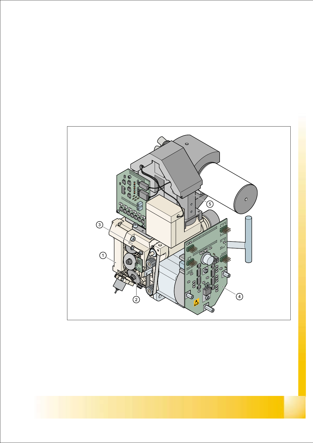
The HS-50 automatic placement system has four 12-segment type DLM1 revolver heads
(item no. 00335700-01). 5
5
Fig. 5.1 - 1 12-segment DLM1 revolver head - overview
(1) Back part, complete / DLM1 (Item no. 00335986-xx)
(2) Star, fitted (Item no. 00341181-xx) with 12 sleeves
(3) Front part, complete / DLM1 (Item no. 00335981-xx)
(4) SP6_12 intermediate distribution board, digital (Item no. 00330648-xx)
(5) 24x24 component camera (Item no. 00320549-xx) / optionally 15,6x15,7 DCA camera (Item
no. 00337450-01)