HS50_advance_level 1_20200522_221201 (1).pdf - 第254页
06/2002 E dition Studen t Guide H S-50 Advance d I 24
Student Guide HS-50 Advanced I 06/2002 Edition
23
8
©
PL EA 1 V GC Training
Version Dec / 00
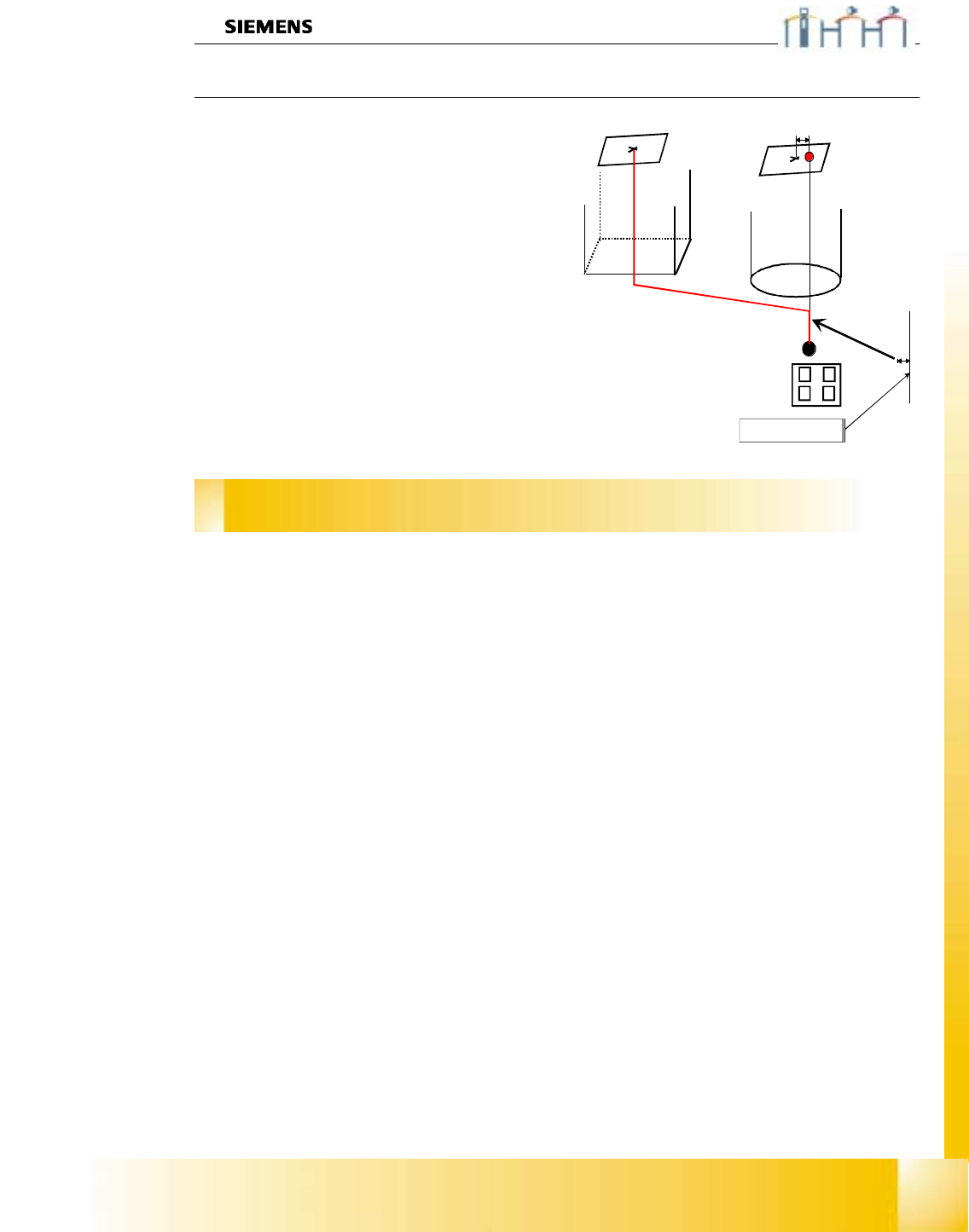
Calibration of SIPLACE HS-50
Machine zero point
Ø With the PCB camera we center the hole
drilled on the fixed transport rail. This position
has fixed X&Y coordinates.
Ø At this mechanical fixed position we calibrate
all gantry axes of 1 placement group area
(maximum is 2 gantries).
Ø With the calculation we consider the actual
valid camera - camera offset.
Ø The Zero point corrections of all gantry axes
are changed about the measured offset.
Ø When the center of the component camera is
exactly above the drilled hole. The axis position
counter shows you the value of
MA_Nullpunkt_X_pg1 /
MA_Nullpunkt_Y_pg1 .
Zero point correction
measured with the PCB camera
fixed distance

06/2002 Edition Student Guide HS-50 Advanced I
24

Student Guide HS-50 Advanced I Ausgabe 06/2002
7.5 Service and Adjustments
25
7.5 Service and Adjustments
checkvacuumsystemifitissealed
Checkaxisdynamic
Takecareaboutgoodconditionsofthe
frictionareaandthecorrektmountingof
thefrictionblocs
Checkbelttensionsofreferingaxis
(differenttensionDLM1C&Pheadsand
theothersseebottom)
A
djustthedistancetothesleeveto
1.3mm
AdjusttheUltrasonicsensors
A
djusttheslowtransportspeed
(notonHS50)
A
djusttheairkissatplacement-
andpickupcircuit
AdjusttheAnti-Crash-board(sHS50)
Zeropointcorr.D-turningaxisP&P
head
ZeropointcorrZ-axisP&P-head
SetCAN-BUSJumper(DIP-switch)
gantry1/2(HS503/4)
AdjustthetracksignalsX/Y-axis
AdjustpositiontracksignalencoderX
/Y-Axisto(0.4mm)
TestupperendstoppositionZ-axis
Adjustmotorpositiontoadistance
plungerhousingof0,2mm
AdjustpositiontracksignalencoderDP-
Axisto1,5mmdistance
Zeropointcorr.star-axisC&P-head
Mountthestarwithzeropointcorr,
gaugeonthestarmotorshaftC&P.
Mounttheplace.starwithpowersupply
onthestarmotorshaftC&P.
Zeropointcorr.Z-axisC&P-head
ReasonfortheAdjustments
Adjustments:
Sequencefromtoptobottom
S/F
Replacesteppermotor
ofvacuumairkiss
S/F
Replaceairkissunit
S/F
Replacelightbarrier
bottomonZ-axis
S/F
S/F
(0)
S/F
S/F
Replacethemotor/belt
oftheZ-axis
S/F
ReplacetheDP-station
S/F
Replacethetracksignal
encoderoftheDP-
station
S/F
Replacethevacuum
distributor
S/F
S/F
S/F
S/F
S/F
ALL
C&P
DLM1
C&P
Dismountreplacethe
placementstar
S/F
S/F
S/F
S/F
ALL
C&P
DLM1
C&P
Replacethestarmotor
S/F
S/F
(0)
S/F
S/F
S/F
ReplaceC&P-head
S/F
S/F
(0)
S/F
S/F
S/F
headmodularity
(C&Phead)
F
F
F
F
ReplaceP&P-head
F
F
F
F
ReplacetheP&P-head-
sleeve
F
F
F
ReplacetheZ-andD-
axismotorP&P-head
S/F
S/F
(0)
Replacethebelt,
changingsattheaxis
S/F
S/F
replacetheX-/Y-motor
S/F
ReplacetheX-axis
frictionblock
S/F
ReplacetheServo
amplifierboard
S/F
S/F
(*)
Replacetheconnecting
boardsmallaxis(X)
S/F
(*)
Replacetheconnecting
boardlargeaxis(Y)
S/F
S/F
Replacetheencoder
X-/Y-axis
S/F
S/F
CounterrorsX-/Y-axis
S/F
ReplacetheUltrasonic
sensor
S/F
Replacethetransport
motor
S/F
Replacehalfbridge
rectifier
OnalltheotherC&Pheadsto
185Hz.
Tracksignaladjustments(*)
notforF5HM
Fcontents80F4/80F5/F5HM
ScontentsHS50/S25HM/(80
S23)/80S20
(0)TheZ-BeltoftheDLM1C&P-
headonHS50/S25HM/(80
S23)/F5HMistoadjustto280
Hz.