HS50_advance_level 1_20200522_221201 (1).pdf - 第355页
06/2002 E dition Studen t Guide H S-50 Advance d I 9 Co nveyor Syst em 14 9 fi g 9.4 - 2 L imit s witc h co nv eyo r w idth ad just me nt, max im um wid ht 9 fi g 9.4 - 3 L imit s witc h co nv eyo r wi dth ad justm e nt,…
Student Guide HS-50 Advanced I 06/2002 Edition
9 Conveyor System
13
9.4 Limit Switch and Proximity Switch
Width Adjust-
ment
9
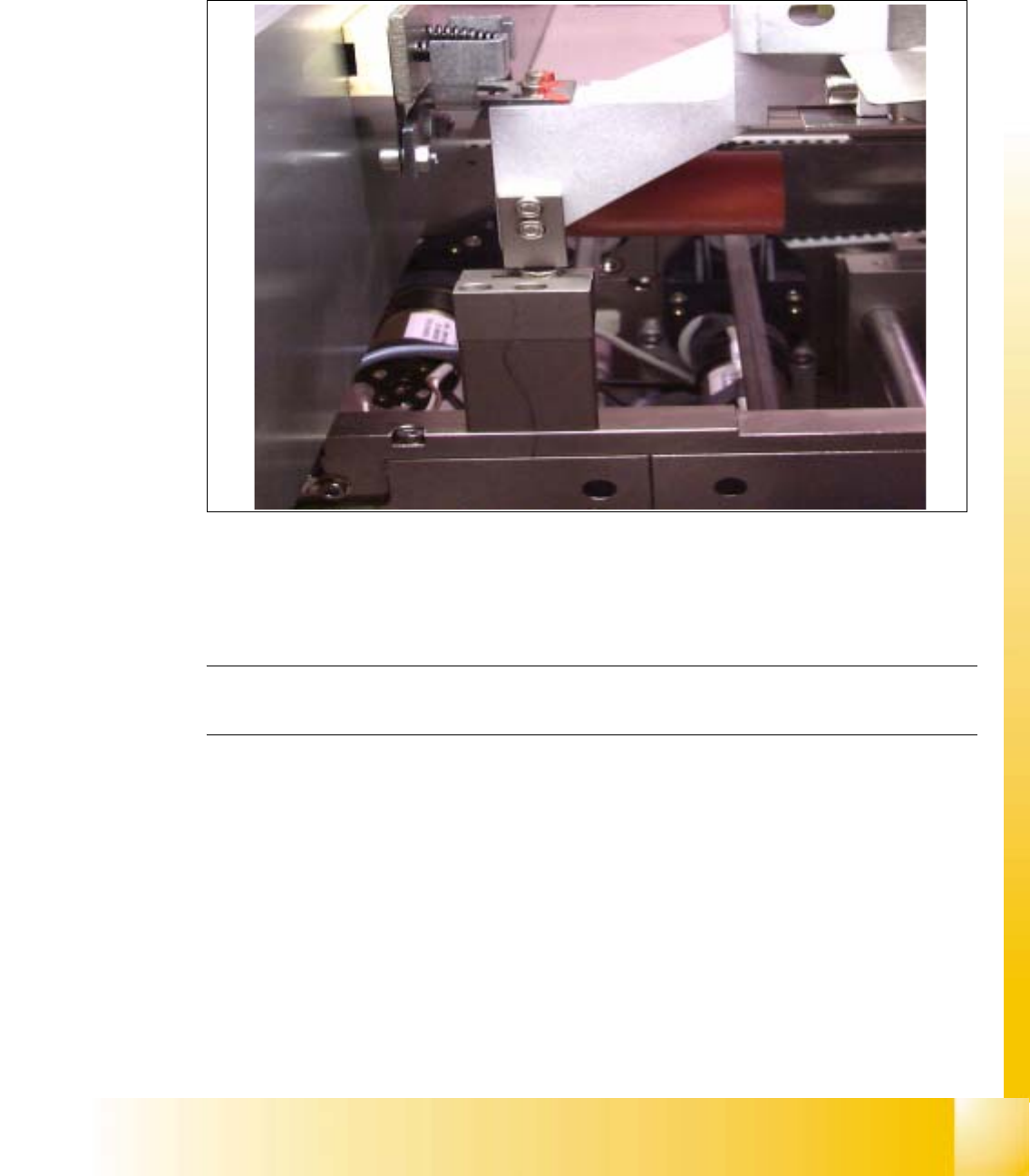
fig 9.4 - 1 Distance of proximity switch
9
➠ Position gantry 2 above the proximity switch.
➠ Set a distance of 0.4 mm.
NOTE
Adjust the second conveyor the same way. 9
06/2002 Edition Student Guide HS-50 Advanced I
9 Conveyor System
14
9
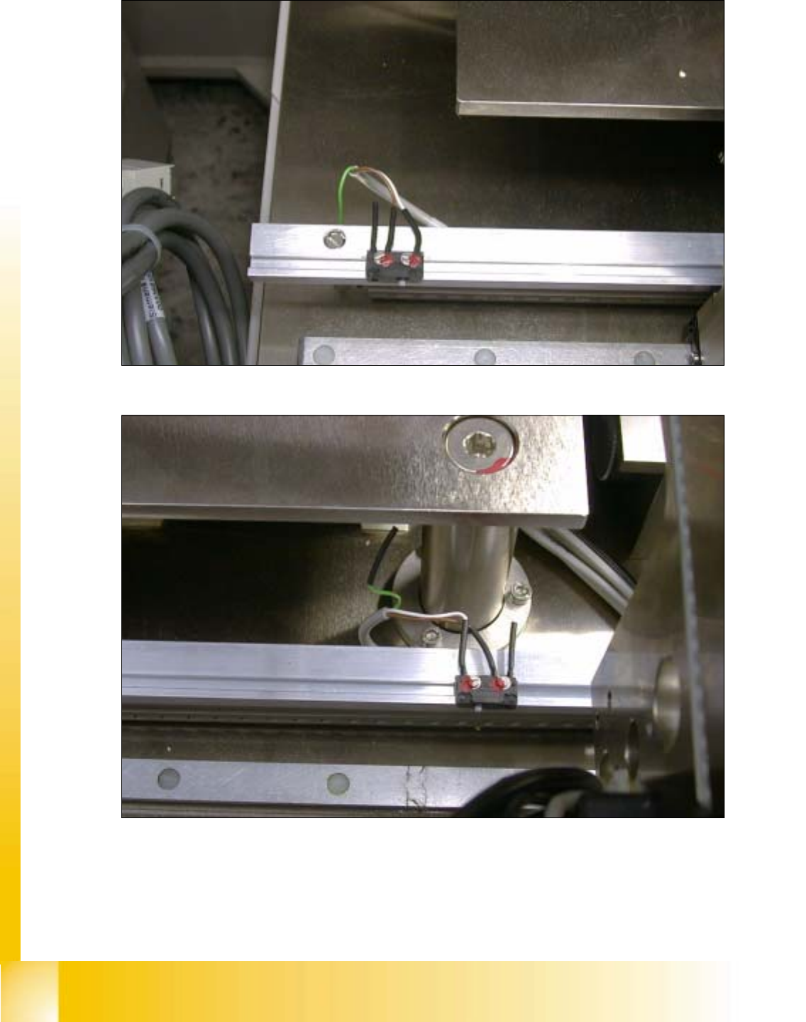
fig 9.4 - 2 Limit switch conveyor width adjustment, maximum widht
9
fig 9.4 - 3 Limit switch conveyor width adjustment, minimum widht
Student Guide HS-50 Advanced I 06/2002 Edition
9 Conveyor System
15
9.5 Lifting table and motor
9.5.1 Functionality of the clamping system
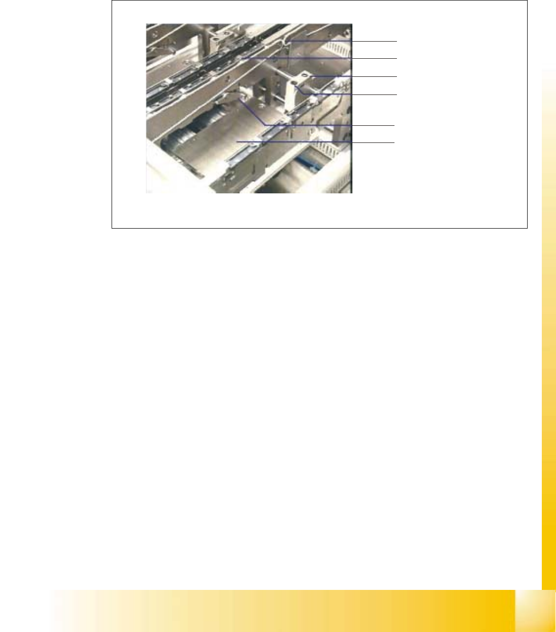
Fig. 9.5 - 1 Clamping system
The PCBs lie on conveyor belts, which are driven by DC motors. The transport process is moni-
tored by means of ultrasonic sensors (proximity switches).
A lifting table is raised by cams and the left- and right-hand clamping combs are applied by means
of a rocking lever.
Conveyor belt
PCB clamp
Stopper
Proximity switc
h
Rocking lever
Lifting table