HS50_advance_level 1_20200522_221201 (1).pdf - 第145页
Studen t Guide HS-50 A dvanced I 06/200 2 Edition 5 DLM1 C&P Head 53 5 Fig. 5.4 - 14 I n ter mediat e distr ibuti on bo ard - so cket X1 0 5. 4.7. 5 Se tti ngs ➠ None
06/2002 Edition Student Guide HS-50 Advanced I
5 DLM1 C&P Head
52
➠ .
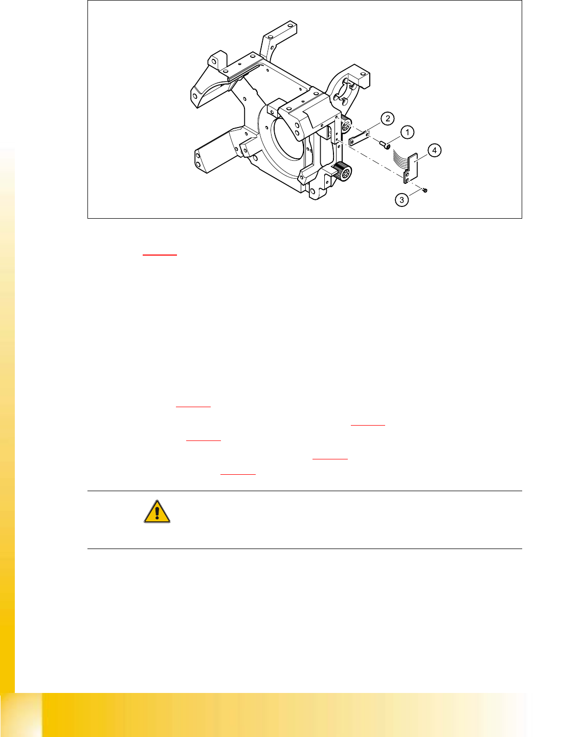
Fig. 5.4 - 13 Replacing the ’Z-axis up’ light barrier board
Key to Fig. 5.4 - 13
(1) 2 x M2.0x4 hexagon socket-head screw
(2) Cable clamp assembly, flat
(3) 2 Phillips screws (1.6x3)
(4) Light barrier board ’Z-axis up’
5.4.7.4 Fitting the z-axis top sensor
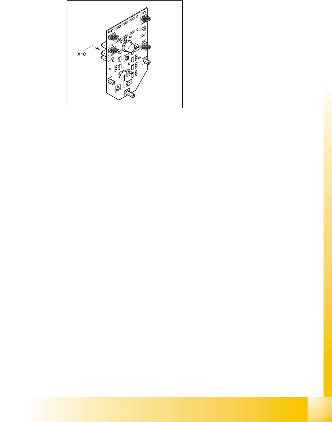
➠ Connect the ribbon cable plug to socket X10 on the intermediate distribution board (see
item X10 in Fig. 5.4 - 14
).
➠ Use the two M1.6x3 Phillips screws (see item 3 in Fig. 5.4 - 13) to fix the light barrier board
(see item 4 in Fig. 5.4 - 13
) in place.
➠ Use the ribbon cable clamp (see item 2 in Fig. 5.4 - 13) and the two hexagon socket-head
screws (see item 1 in Fig. 5.4 - 13
) to fix the ribbon cables.
CAUTION 5
Make sure that the ribbon cable is not squashed in the guide channel. 5
Student Guide HS-50 Advanced I 06/2002 Edition
5 DLM1 C&P Head
53
5
Fig. 5.4 - 14 Intermediate distribution board - socket X10
5.4.7.5 Settings
➠ None
06/2002 Edition Student Guide HS-50 Advanced I
5 DLM1 C&P Head
54
5.4.8 Replacing the z-axis bottom sensor
5.4.8.1 Tools and equipment
– Set of DIN 911 Allen keys
– Set of Phillips screwdrivers
– Test probe, 1.3 mm Ø, article number 00326163-01
– Gauge for the star (collect&place head / DLM1), article number 00326164-01
– Power pack for the collect&place head / DLM1, article number 00353277-01
– Tray for transporting the collect&place head
– Laboratory gloves
5.4.8.2 Parts
Sensor for "Z-axis down", article number 00321524-04 5
5.4.8.3 Dismantling the z-axis bottom sensor
➠ Dismantle the front part of the collect&place head as described in section 5.4.3.2, page 5 - 36.
➠ Place the front part of the collect&place head on the tray.
➠ Dismantle the star as described in section 5.4.5.3, page 5 - 43.
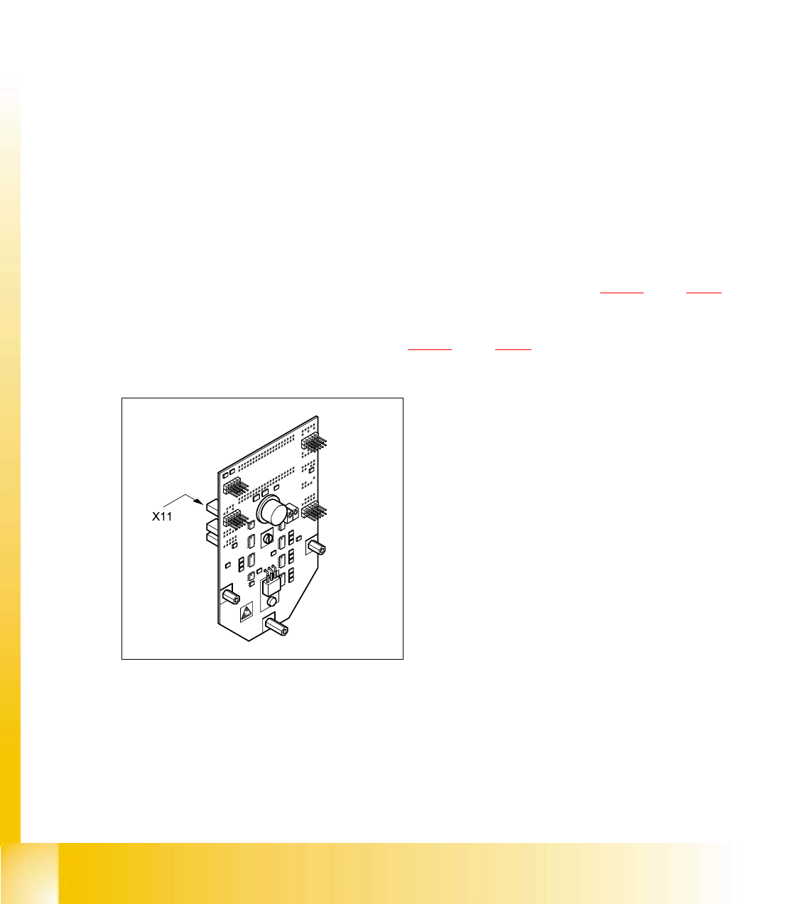
➠ Remove the plug connector from socket X11 on the intermediate terminal block.
5
Fig. 5.4 - 15 Intermediate terminal block, socket 11
5