HS50_advance_level 1_20200522_221201 (1).pdf - 第147页
Studen t Guide HS-50 A dvanced I 06/200 2 Edition 5 DLM1 C&P Head 55 5 Fig. 5.4 - 16 R emo ving / i nstal lin g the "Z -ax is dow n" sensor (1) "Z-axis down" sensor (2) Sl ot screw M1.6x3 ,2 (3) J…
06/2002 Edition Student Guide HS-50 Advanced I
5 DLM1 C&P Head
54
5.4.8 Replacing the z-axis bottom sensor
5.4.8.1 Tools and equipment
– Set of DIN 911 Allen keys
– Set of Phillips screwdrivers
– Test probe, 1.3 mm Ø, article number 00326163-01
– Gauge for the star (collect&place head / DLM1), article number 00326164-01
– Power pack for the collect&place head / DLM1, article number 00353277-01
– Tray for transporting the collect&place head
– Laboratory gloves
5.4.8.2 Parts
Sensor for "Z-axis down", article number 00321524-04 5
5.4.8.3 Dismantling the z-axis bottom sensor
➠ Dismantle the front part of the collect&place head as described in section 5.4.3.2, page 5 - 36.
➠ Place the front part of the collect&place head on the tray.
➠ Dismantle the star as described in section 5.4.5.3, page 5 - 43.
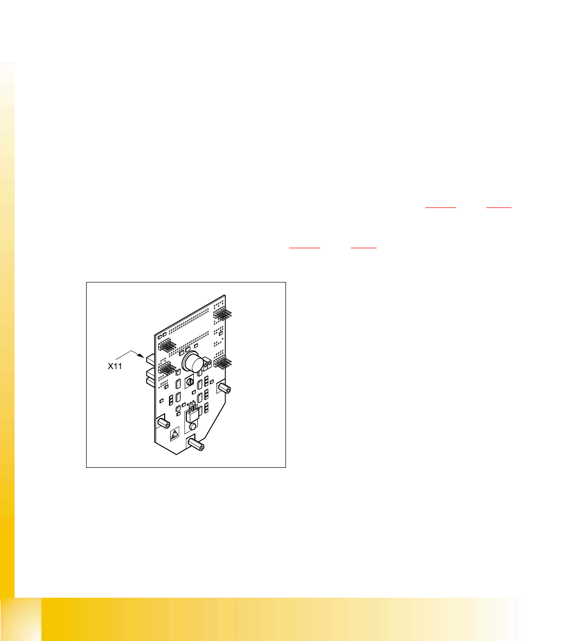
➠ Remove the plug connector from socket X11 on the intermediate terminal block.
5
Fig. 5.4 - 15 Intermediate terminal block, socket 11
5
Student Guide HS-50 Advanced I 06/2002 Edition
5 DLM1 C&P Head
55
5
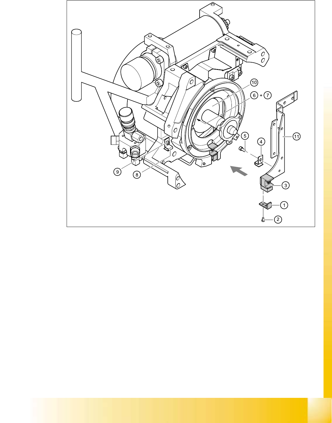
Fig. 5.4 - 16 Removing/installing the "Z-axis down" sensor
(1) "Z-axis down" sensor
(2) Slot screw M1.6x3,2
(3) Jaws for the Z-axis
(4) Cable bearer for light barrier 3 / DLM1
(5) M2x3 hexagon socket head screw
(6) Angled clip / DLM1 (beside the star drive)
(7) M2.5x4 hexagon socket head screw
(8) Angled clip / DLM1
(9) M2.5x4 hexagon socket head screw
(10) Star drive
(11) Driver / DLM1
(12) Cable clamp on driver / DLM1
(13) M2x5 hexagon socket head screw
06/2002 Edition Student Guide HS-50 Advanced I
5 DLM1 C&P Head
56
➠ Push the Z-axis down.
➠ Undo the two M1.6x3,2 slot screws (item 2 in Fig. 5.4 - 16).
➠ Loosen the M2x3 hexagon socket-head screw (item 5 in Fig. 5.4 - 16) of the cable clamp (item
4 in Fig. 5.4 - 16
).
➠ Undo the M2x5 hexagon socket-head screw (item 13 in Fig. 5.4 - 16) of the cable clamp
(item 12 in Fig. 5.4 - 16
).
➠ Undo the M2.5x4 hexagon socket-head screw (item 7 in Fig. 5.4 - 16) on the angled clip (item
6 in Fig. 5.4 - 16
) beside the star drive.
➠ Undo the M2.5x4 hexagon socket-head screw (item 9 in Fig. 5.4 - 16) on the angled clip (item
8 in Fig. 5.4 - 16
).
➠ Carefully pull the sensor and cable out of the front part of the collect&place head.
5.4.8.4 Installing the z-axis bottom sensor
➠ Thread the sensor cable from the Z-axis into the front part of the collect&place head.
➠ Fix the sensor (item 1 in Fig. 5.4 - 16) in position using the two M1.6x3,2 slot screws (item 2 in
Fig. 5.4 - 16
). Initially screw only loosely into the jaws for the Z-axis (item 3 in Fig. 5.4 - 16).
➠ Use the M2x3 hexagon socket-head screw (item 5 in Fig. 5.4 - 16) to fix the cable clamp for
light barrier 3 (item 4 in Fig. 5.4 - 16
) in place.
➠ Fix the cable in place using the cable clamp (item 12 in Fig. 5.4 - 16) in the driver (item 11 in
Fig. 5.4 - 16
).
➠ Fix the cable in place using the angled clip (item 6 in Fig. 5.4 - 16) beside the star drive.
➠ Check the cable run inside the front part of the collect&place head.
– When the Z-axis is pushed right out, the cable should lie loosely around the housing for the
star drive shaft. The cable must NOT be pulled tight.
– When the Z-axis is pushed right in, the cable should run freely inside the front part of the
collect&place head without touching the rotary encoder for the DP-axis.
CAUTION
If the radius of curvature is too small, the Z-axis may become jammed or the light barrier
cable may break. 5
If the cable run meets the two conditions above, fix the cable in place using the angled clip
(item 8 in Fig. 5.4 - 16
). 5
➠ Insert the plug connector for the cable into socket X11 on the intermediate terminal block.