HS50_advance_level 1_20200522_221201 (1).pdf - 第384页
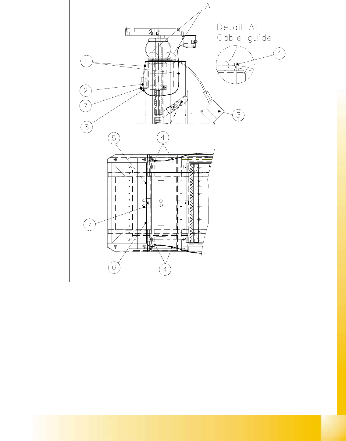
S tud ent Guid e HS-50 A dvanced I Editi on 06/2 002 10 Co mpon ent Cha ngeov er T ab le 19 10 Fig. 10. 5.3 Cabl e Guide at the C ompo nent Change over T able Key: 1) "Cabl e /component table assy " (with prote…

Edition 06/2002 Student Guide HS-50 Advanced I
10 Component Changeover Table
18
10.5.4 Exchanging the "Cable/Component Table"
The component changeover table has been disassembled and prepared as described in Sec-
tion 10.5.1.
à Unplug the interface connector and the power supply connector of the component table cable
from the back of the communications unit (see Fig. 10.5.3).
à Undo the screw next to this which fastens the grounding cable (lug) to the housing of the com-
munications unit (Allen wrench size 4).
à Disconnect the 5 bar pneumatic hose at the quick-release coupling of the bellows cylinder (see
Fig. 10.5.1 -> 6).
At this time, the 2.3 bar pneumatic hose of the component table air supply is not connected.
NOTE:
The "Cable/component table" consists of:
- Interface cable with plug
- Power supply cable with plug
- Grounding cable with cable lug
- Pneumatic hose for 5 bar, with connector (supply to bellows cylinder for component table)
- Pneumatic hose for 2.3 bar with filler plug (furnished for component table/air supply). 10
à Use the new "Cable/component table assembly" (Item No.: see Section 10.3) and insert it into
the cable harness from the top down (cable harness: see Fig. 10.5.3 -> 7).
à Place the hex nut under the cable harness onto the protective hose and screw the hose / cable
securely (= strain relief).
à Run the component table cable through the recess with the edge guard at the top (see Fig.
10.5.3).
à Make the plug-and-socket connection of the interface cable and power supply cable to the con-
trol board of the communications unit (see Fig. 10.5.4). Different plugs makes certain that the
assignment is correct.
à Connect the 5 bar pneumatic hose, which was run in the "Cable/component table", to the
quick-release coupling of the bellows cylinder and tighten the hex nut.
NOTE:
The second compressed air hose (currently with dummy plug) is furnished to connect the compo-
nent table air supply to the pneumatic hose for 2.3 bar. It is not connected at this time. 10
10
Student Guide HS-50 Advanced I Edition 06/2002
10 Component Changeover Table
19
10
Fig. 10.5.3 Cable Guide at the Component Changeover Table
Key:
1) "Cable/component table assy" (with protective hose)2) 2 Connectors (interface and power
supply) and 2 Pneumatic hoses
(2.3 bar and 5 bar)
3) Connectors for connection to machine base 4) Cable gland bolts
5) Cable gland for component changeover table1 or 3 6) Cable bland for comp. changeover
table 2 or 4
7) Cable harness (= strain relief) 8) Hex nut/counter nut (PG coupling)
Edition 06/2002 Student Guide HS-50 Advanced I
10 Component Changeover Table
20
à Screw the cable lug from the ground cable to the housing of the communications unit.
While doing so, insert the contact lock washer and the spring lock washer (see Fig. 10.5.4 ->
2).
à Run the free section of cable between the cable holders (bolts) at left or right under the com-
ponent table, as shown in Fig. 10.5.3.
à Run the cable out to the left or right, depending on the position of the component changeover
table which was moved into the machine.
à Perform the "Final Steps".
10.5.5 Exchanging the Communications Unit / Exchanging the Edge Guard if
Necessary
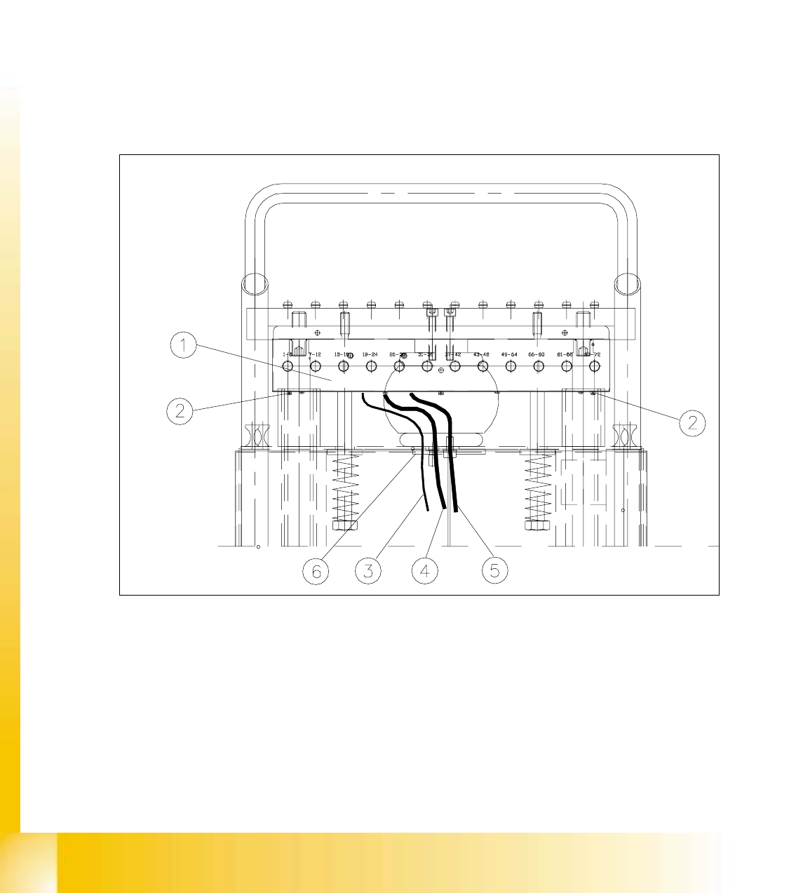
Fig. 10.5.4 Exchanging the Communications Unit; View in Direction "Component Table Termination Panel"
Key:
1) Communications unit 2) Fastening for communications unit,
2 Socket hex cap screws M5 x 6,
3) Grounding cable 4) Power supply cable
5) Interface cable 6) Edge guard for cable gland