HS50_advance_level 1_20200522_221201 (1).pdf - 第244页
06/2002 E dition Studen t Guide H S-50 Advance d I 7 Calibr ation 14 0 f ig 7. 3 - 18 Di sp lay: " Gan try fu ncti on s" 0 f ig 7. 3 - 19 Di sp lay: " Axis fu nc tion s" 7.3.9 Det erminatio n of T r a…
Student Guide HS-50 Advanced I 06/2002 Edition
7 Calibration
13
0
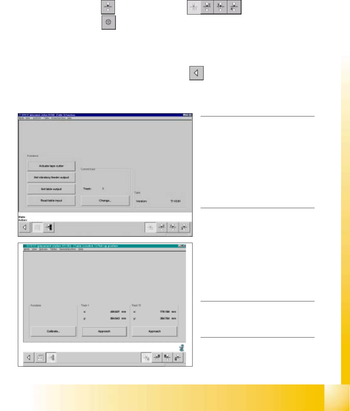
fig 7.3 - 16 Display: "Functions of the component table"
fig 7.3 - 17 Display: "Pick-up position"
NOTE
Make sure that the calibration data for the
PCB camera, the segment offset II (C&P -
PCB camera offset) and the machine zero
point have been determined already.
Before you use the gauge, make sure that
the appropriate component table under
the gauge is free of unevenness and dirt.0
0
0
0
0
0
0
0
0
0
0
NOTE
Measuring the component tables 2, 3 and
4, proceed the same way. 0
0
0
0
0
7.3.8 Calibration of the Component Table
Example: Component table 1 7
SITEST: 7
à Select "Component tables" ==> "Component table 1" ==>
"Calibrate pick-up position" .
à Set the gauge to track1 of the component table 1.
à Select "Calibrate (field "track1") ==> "OK".
à Set the gauge to track 72 of the component table 1.
à Select "Calibrate (field "track 72") ==> "OK" ==> "Main View" ==> "Settings" ==> "Save machine data".
06/2002 Edition Student Guide HS-50 Advanced I
7 Calibration
14
0
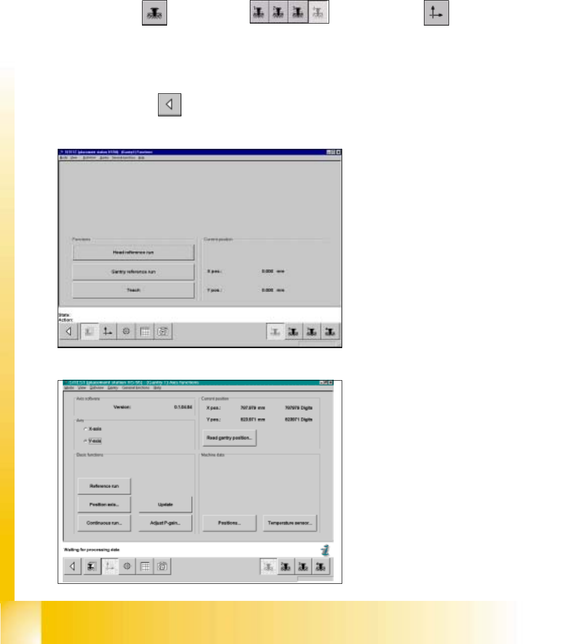
fig 7.3 - 18 Display: "Gantry functions"
0
fig 7.3 - 19 Display: "Axis functions"
7.3.9 Determination of Traversing Paths of Gantry Axes
7.3.9.1 Maximum Traversing Path Y-Axis Gantry 4 (3)
à Manually, move the gantry 4 (3) up to 35 mm to the left hand machine stop.
SITEST: 7
à Select "Gantry" ==> "Gantry 4 (3) ==> "Axis functions" ==> "Y-axis" ==>
"Positions...".
à Edit the value for the current position of the y-axis under "Maximum position [dgts]" and
accept.
à Perform a reference run.
à Select "Main View" ==> "Settings" ==> "Save machine data".
Student Guide HS-50 Advanced I 06/2002 Edition
7 Calibration
15
0
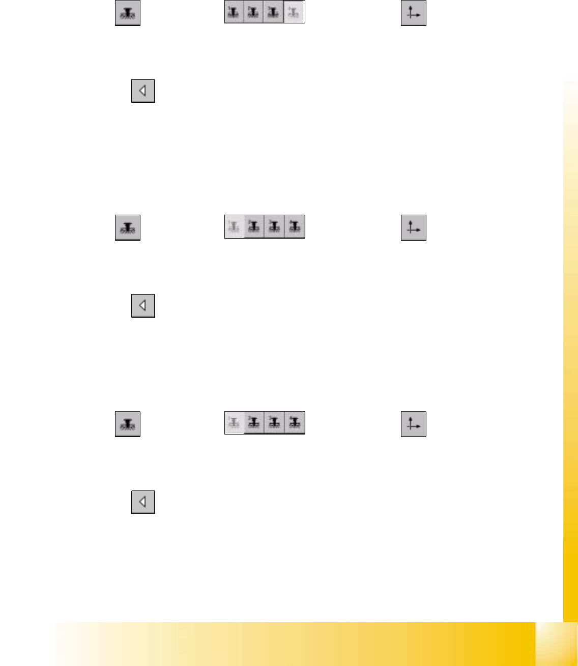
7.3.9.2 Minimum Traversing Path Y-Axis Gantry 4 (3)
à Manually, move gantry 1 (2) up to a distance of 35 mm to the right hand machine stop.
à Now, move gantry 4 (3) to a distance of 35 mm from gantry 1 (2).
SITEST: 7
à Select "Gantry" ==> "Gantry 4 (3) ==> "Axis functions" ==> "Y-axis" ==>
"Positions ...".
à Edit the value for the current position of the y-axis under "Minimum position [dgts]" and accept the value.
à Perform a reference run.
à Select "Main View" ==> "Settings" ==> "Save machine data".
7.3.9.3 Maximum Traversing Path Y-Axis Gantry 1 (2)
à Manually, move gantry 4 (3) to a distance of 35 mm to the upper machine stop.
à Now, move gantry 1 (2) to a distance of 35 mm to gantry 4 (3).
SITEST: 7
à Select "Gantry" ==> "Gantry 1 (2) ==> "Axis functions" ==> "Y-axis" ==>
"Positions ...".
à Edit this value for the current position of the y-axis under "Maximum position [dgts]" and accept the value.
à Perform a reference run.
à Select "Main View" ==> "Settings" ==> "Save machine data".
7.3.9.4 Minimum Traversing Path Y-Axis Gantry 1 (2)
à Manually, move gantry 1 (2) to a distance of 35 mm to the right hand machine stop.
SITEST: 7
à Select "Gantry" ==> "Gantry 1 (2) ==> "Axis functions" ==> "Y-Axis" ==>
"Positions ...".
à Edit the value for the current position of the y-axis under "Minimum position [dgts]" and accept the value.
à Perform a reference run.
à Select "Main View" ==> "Settings" ==> "Save machine data".