HS50_advance_level 1_20200522_221201 (1).pdf - 第51页
Studen t Guide HS-50 A dvanced I 06/200 2 Edition 2 Overview 21 2.4. 8 Ballas t Circuit Fig. 2.4 - 9 Se rvo c age, Ba llas t Cir cui t 2.4.9 Power S u pply Ser vo lo gic Fig. 2.4 - 10 S e rvo c age, Pow er su pply Ser v …
06/2002 Edition Student Guide HS-50 Advanced I
2 Overview
20
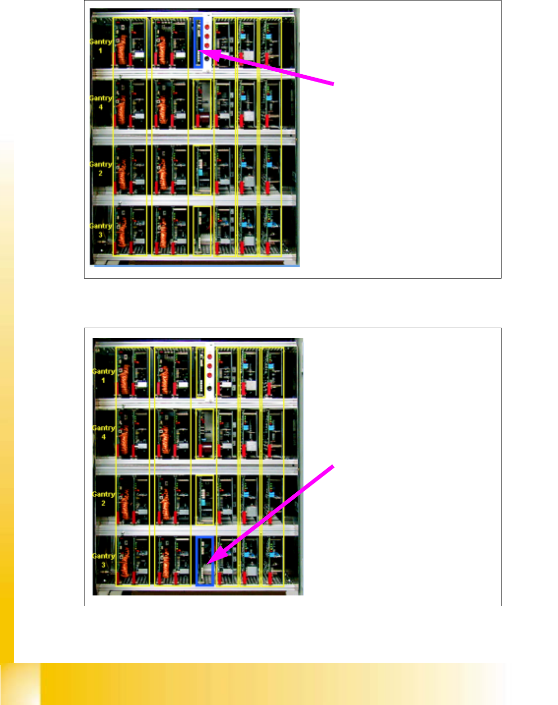
2.4.6 Anti-Crash-Board Placement Area 1
Fig. 2.4 - 7 Servo cage, Anti-Crash-Board Placement Area 1
2.4.7 Anti-Crash-Board Placement Area 2
Fig. 2.4 - 8 Servo cage, Anti-Crash-Board Placement Area 2
Anti-Crash-Board PC1
Anti-Crash-Board PC2
Student Guide HS-50 Advanced I 06/2002 Edition
2 Overview
21
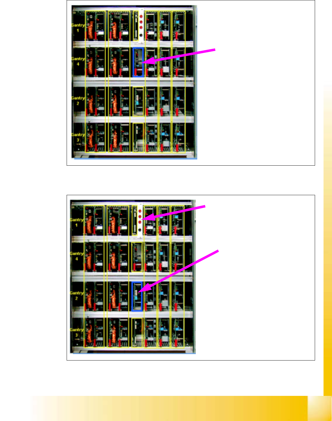
2.4.8 Ballast Circuit
Fig. 2.4 - 9 Servo cage, Ballast Circuit
2.4.9 Power Supply Servo logic
Fig. 2.4 - 10 Servo cage, Power supply Servo logic
Ballast Circuit
Power supply unit +/-15V
for servo card logic
Measurement points in the servo unit:
+ 200 V for the main axes (X,Y)
+ 4V / 100 V star axes
+ 30 V head axes (z,dp)
06/2002 Edition Student Guide HS-50 Advanced I
2 Overview
22
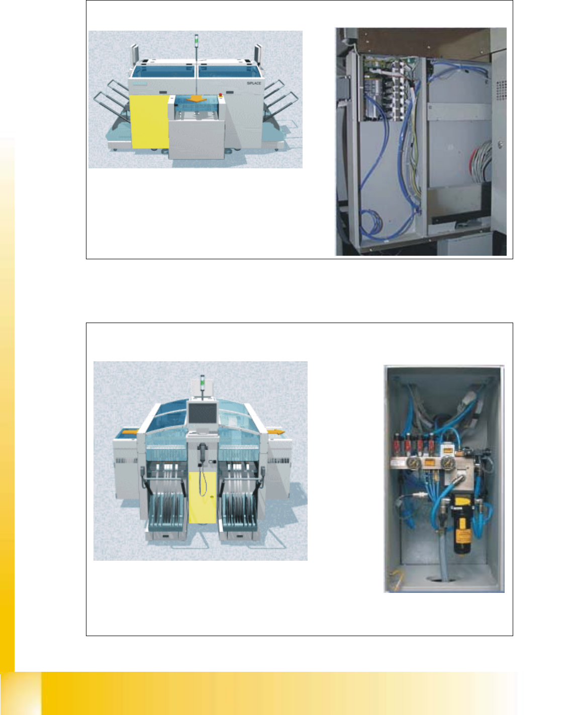
2.5 Sector 2
Fig. 2.5 - 1 Sector 2, CAN bus adapter
2.6 Pneumatic Cage
Fig. 2.6 - 1 Pneumatic cage
CAN bus adapterPCB output side
Sector 2 contains the CAN bus adapter for the
changeover table of gantry 2
Right view (operator controls)
Pneumatic unit
The pneumatic unit is used to prepare and distribute the
compressed air required in the machine. The pressure in the
compressed-air connection is 5,1 bar with a consumption level of 1200 Nl/min