HS50_advance_level 1_20200522_221201 (1).pdf - 第563页
06/2002 Edition S tudent Gui de HS- 50 Advanced I 20 App endix 36 NOTE The current state of a bit can also be in verted if the corresponding LED sym bol i s selected by do uble-clicking on it. 20 NOTE Please no te that a…
Student Guide HS-50 Advanced I 06/2002 Edition
20 Appendix
35
Outputs 20
– In the "Inputs" display click on the icon to switch to the "Outputs" display.
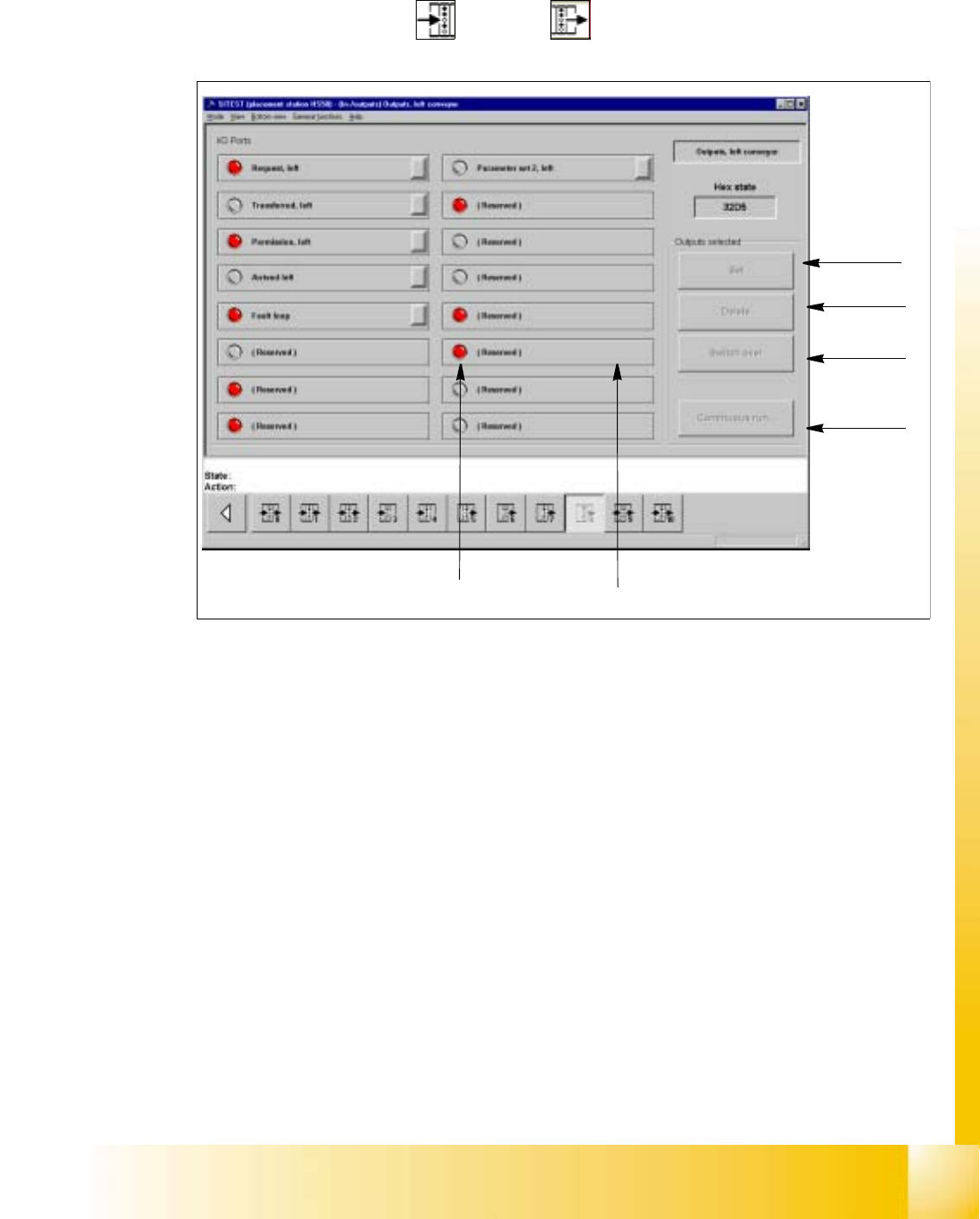
Fig. 20.4 - 9 "Outputs" Display
Key:
a to set the selected bits
s to reset the selected bits
d to invert the current state
f to convert the state of the selected bits in the continuous run
g selected bit (output)
h LED symbol
– Activate the appropriate radio button of the port containing the output group you wish to test.
– Click on the check boxes next to the function descriptions of the outputs you wish to test,
or click directly on the function descriptions.
– Click on the button indicating the desired function. The selected function will be carried out.
1
2
3
4
5
6

06/2002 Edition Student Guide HS-50 Advanced I
20 Appendix
36
NOTE
The current state of a bit can also be inverted if the corresponding LED symbol is selected
by double-clicking on it. 20
NOTE
Please note that a waiting time needs to be entered prior to the execution of the continuous
run. 20
– Click on the Continuous run button.
A dialog box for entering the waiting time opens.
– Enter the desired waiting time and then start the continuous run by clicking on the Start but-
ton.
– Terminate the continuous run by clicking on the Cancel button in the "Continuous run" dia-
log box.
Student Guide HS-50 Advanced I 06/2002 Edition
20 Appendix
37
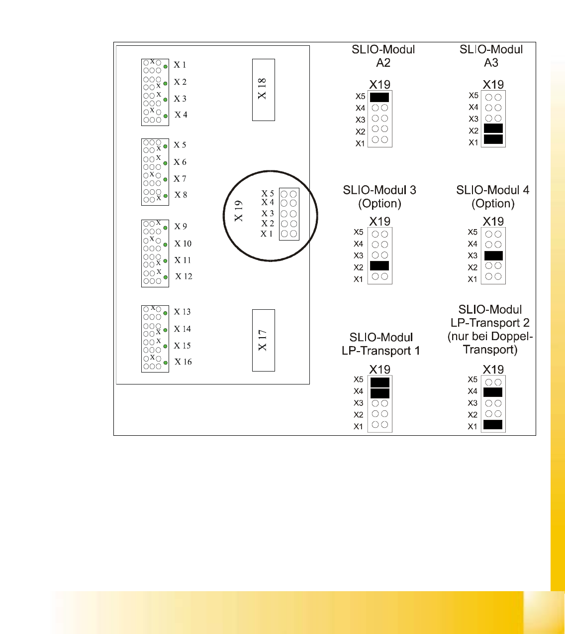
20.4.6.2 SLIO Moduls
All SLIO-Moduls are controlled either by the fast or the slow CAN-Bus. While the fast CAN-Bus
controlls head funktions, cutting devices and the component tables, the slow CAN-Bus handles
the nozzle changers and conveyor functions.
All this the general function of the SLIO’s to transfere the logical signals from the CAN-Bus into
24V signals on the output side or otherwise to transfer the 24V input signals to an appropiate level
for the CAN-Bus.
Fig. 20.4 - 10 Jumper settings SLIO Moduls