HS50_advance_level 1_20200522_221201 (1).pdf - 第38页
06/2002 E dition Studen t Guide H S-50 Advance d I 2 Ov erview 8 2 F ig. 2. 1 - 2 Volta ges on th e fr ont pa ne l of th e p owe r s upp ly unit 246 135 F3 135 246 SZ1 K14 K12 K1 1 13 5 24 6 MS1A MS1 S1 MS5 MS6 MS4 MS3 1…

Student Guide HS-50 Advanced I 06/2002 Edition
2 Overview
7
2.1.1 Supply voltages
The power supply unit is located in the left-hand middle section of the placement system. A lock-
able door prevents access to the unit. 2
The power supply unit provides the following supply voltages: 2
– 200 VDC for the servo amplifiers of the x and y axes
– 100 VDC/4 VDC for the servo amplifiers of the star
– 30 VDC for the servo amplifiers the z and dp axes
– 52 VDC for the DC/DC converters in the control unit
– 40 VDC for the component tables and the PCB handling system
– 10 VDC for the component tables
– 3 x 230 VAC for the lifting table motors of the single or dual conveyor (option)
– 230 VAC for the station computer and monitors
For the service socket 2
PLEASE NOTE: The service socket can only be used if the placement system is con-
nected to the main power supply with a 5-conductor cable (L1, L2, L3, N, PE). 2
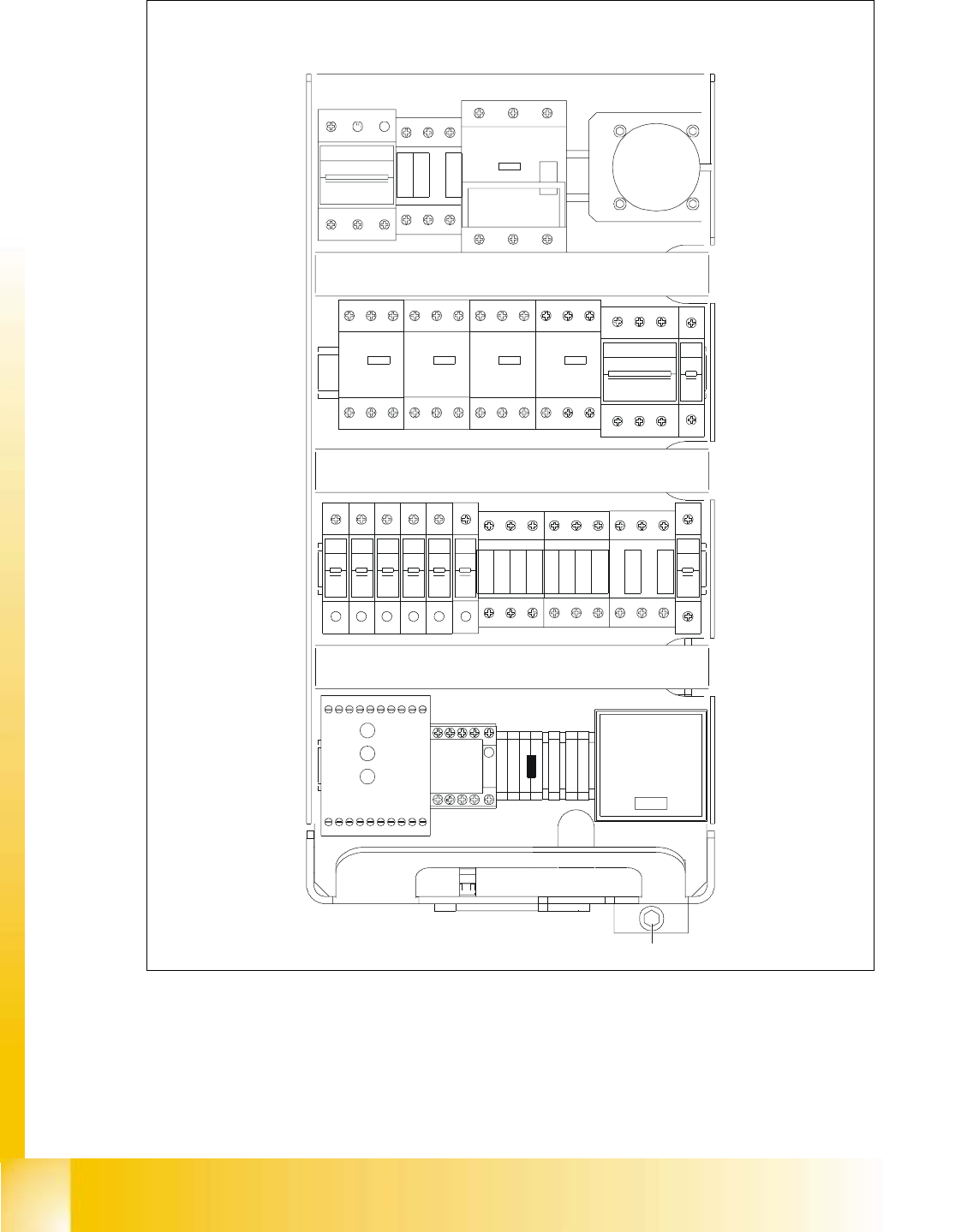
2.1.2 Voltages on the front panel of the power supply unit
PLEASE NOTE: The placement system must be started in order to take these measurements.
This means that the protective covers and component flaps must be closed and the component
tables docked. The emergency stop button must be released and the Start button pressed. If this
is not the case, the operating voltages will not be switched through to the servo amplifiers, lifting
tables, etc. 2
The inputs to the modules all have odd numbers and the outputs have even numbers. 2
In the case of fuses (F1, etc), the input is always on the underside of the module, whereas with
contactors (SZ1, etc) and motor circuit-breakers (MS1 ...), it is always at the top. 2
230 VAC (Europe) Input 3 x 400 VAC
115 VAC (U. S. A.) Input 3 x 204 VAC
130 VAC (other) Input 3 x 230 VAC
220 VAC (other) Input 3 x 380 VAC
240 VAC (other) Input 3 x 415 VAC
06/2002 Edition Student Guide HS-50 Advanced I
2 Overview
8
2
Fig. 2.1 - 2 Voltages on the front panel of the power supply unit
246
135
F3
135
246
SZ1
K14
K12
K11
135
246
MS1A
MS1
S1
MS5 MS6MS4MS3
135
2 64 2 64
1 53 31 5
42 6 624
513
F4
426
31 5
F10F9F8F7F6F5
111111
222 222
F1
2
1
SZ2 SZ3 SZ23
246
135135
2462 46
1
3 5
K232
K234
K34
K33
K32
K31
K21
K22
K23
K24
SSK
1 375
4268
A1+
A2-
SZ4
X1
VUWW
PE
PE
N
BU1
M8
F11
2
1
54 6614 24 4434X4 X6L-
13L+ X3X1 X5 533323 43 65
Netz
Power
Channel 1
Kanal 1
Channel 2
Kanal 2
Student Guide HS-50 Advanced I 06/2002 Edition
2 Overview
9
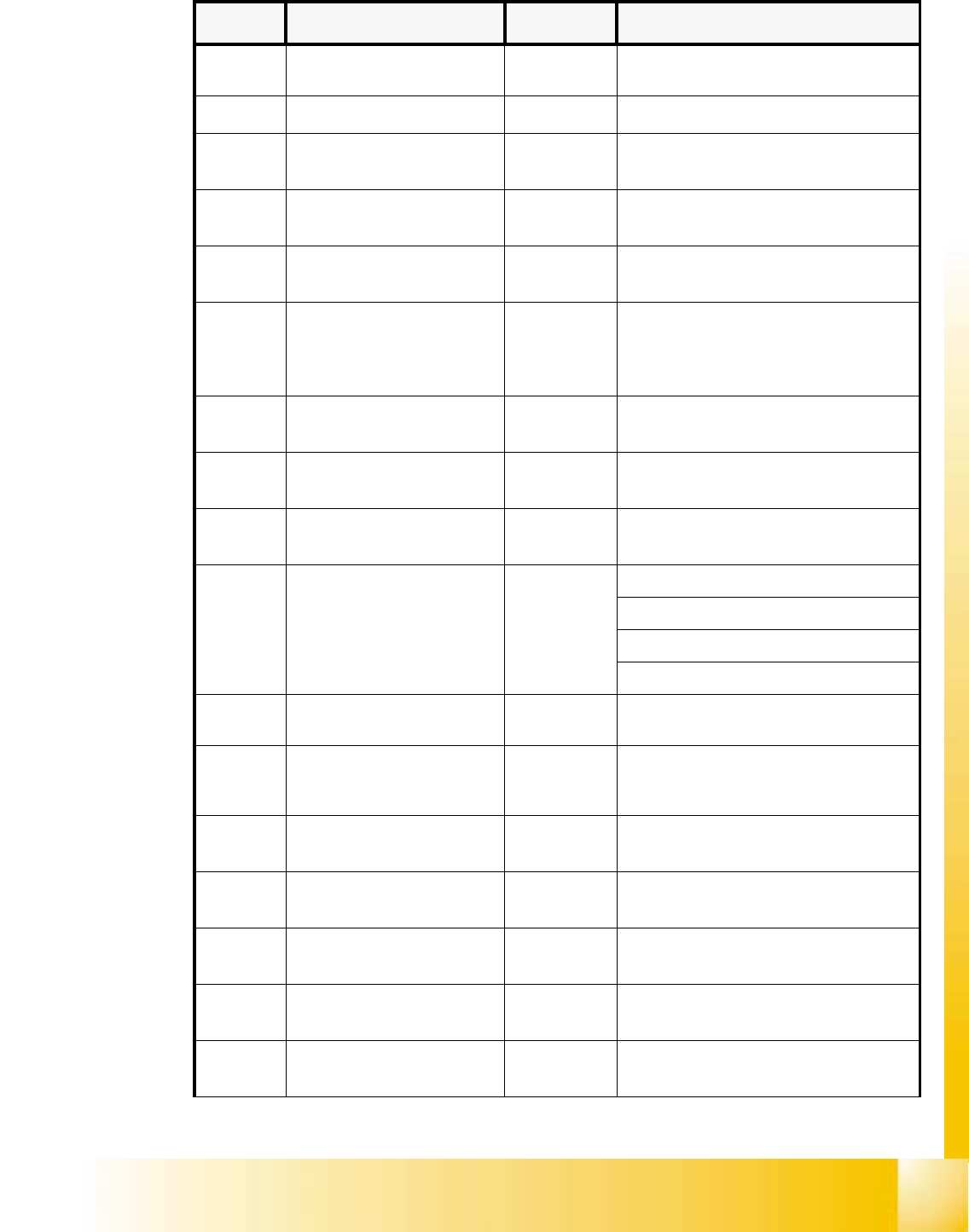
Module Designation Clamps Voltages
X1
connecting terminal panel
power supply
U, V, W
3 x 204 VAC / 3 x 380 VAC /
3 x 400 VAC / 3 x 415 VAC
BU1
service socket 115 VAC / 220 VAC / 230VAC / 240 VAC
S1
main switch
1, 3, 5 u.
2, 4, 6
3 x 204 VAC / 3 x 380 VAC /
3 x 400 VAC / 3 x 415 VAC
MS1
motor protective switch
1, 3, 5 u.
2, 4, 6
3 x 204 VAC / 3 x 380 VAC /
3 x 400 VAC / 3 x 415 VAC
SZ1
main contactor
1, 3, 5 u.
2, 4, 6
3 x 204 VAC / 3 x 380 VAC
3 x 400 VAC / 3 x 415 VAC
MS3
MS4
MS5
MS6
motor protective switch
PCB conveyor 1
motor protective switch
PCB conveyor 2 (option)
1, 3, 5 u.
2, 4, 6
1, 3, 5 u.
2, 4, 6
3 x 230 VAC
3 x 230 VAC
3 x 230 VAC
3 x 230 VAC
SZ2
contactor
1, 3, 5
2, 4, 6
3 x 140 VAC
3 x 140 VAC
SZ3
contactor
1, 3, 5
2, 4, 6
3 x 140 VAC
3 x 140 VAC
SZ23
contactor
1, 3, 5
2, 4, 6
3 x 140 VAC
3 x 140 VAC
SZ4
contactor
A1 (+) - A2 (-)
1, 2
3, 4
5, 6
24 VDC
24 VDC against ground
24 VDC against ground
24 VDC against ground
SSK
protective contactor
combination
L+, X3, X5 24 VDC against ground
F1
fuse
service socket
1, 2
115 VAC / 220 VAC
230 VAC / 240 VAC
against N on the connecting terminal panel 1
F3
fuse
board net
1, 3, 5
2, 4, 6
3 x 230 VAC
F4
fuse
x- / y- axis
1, 3, 5
2, 4, 6
3 x 140 VAC
F5
fuse
star - axis
1, 2 100 VDC against minus of rectifier V3.
F6
fuse
z- and dp - axis
1, 2 30 VDC against minus of rectifier of V4.
F7
fuse
component table (feeder)
1, 2
38 VDC against minus of rectifier V5.