HS50_advance_level 1_20200522_221201 (1).pdf - 第559页
06/2002 Edition S tudent Gui de HS- 50 Advanced I 20 App endix 32 20.4.5 .5 Air kiss at pl a cement or at reject posit ion Fig . 20.4 - 7 A i r ki ss at pla cemen t or a t reje ct pos iti on 1. Air kiss is applie d at pl…
Student Guide HS-50 Advanced I 06/2002 Edition
20 Appendix
31
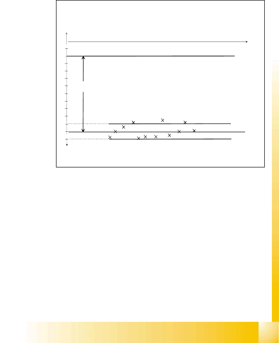
20.4.5.4 Vacuum check “segment sealed” before pick up
Fig. 20.4 - 6 Vacuum check “segment sealed” before pick up
1. The quality of the segment seal is checked prior to each pick up.
2. This tests the quality of the seal given by the vacuum pluneer.
3. Normally the result should be within ± 20 mbar of the closed result determined during refer-
ence.
4. If a result is outside the tolerance, then the machine logs an error. If the error occurs 3 times
within 350 placements at the same segment, an error is reported "Leaky segment".
5. If this error occurs check the condition of the value plunger.
6. The values for 20 mbar, 3 errors and 350 placements are in the vacuum.MA file.
-700
-720
-740
-760
-780
-800
-820
-840
-860
-880
-900
0
t
-920
Threshold -20 mbar
Threshold +20 mbar
Vacuum difference
at reference run
1.Error on this
segment is logged
2. Error logged
3. Error on this
segment is displayed
Pressure difference nozzle - inside -> environment
06/2002 Edition Student Guide HS-50 Advanced I
20 Appendix
32
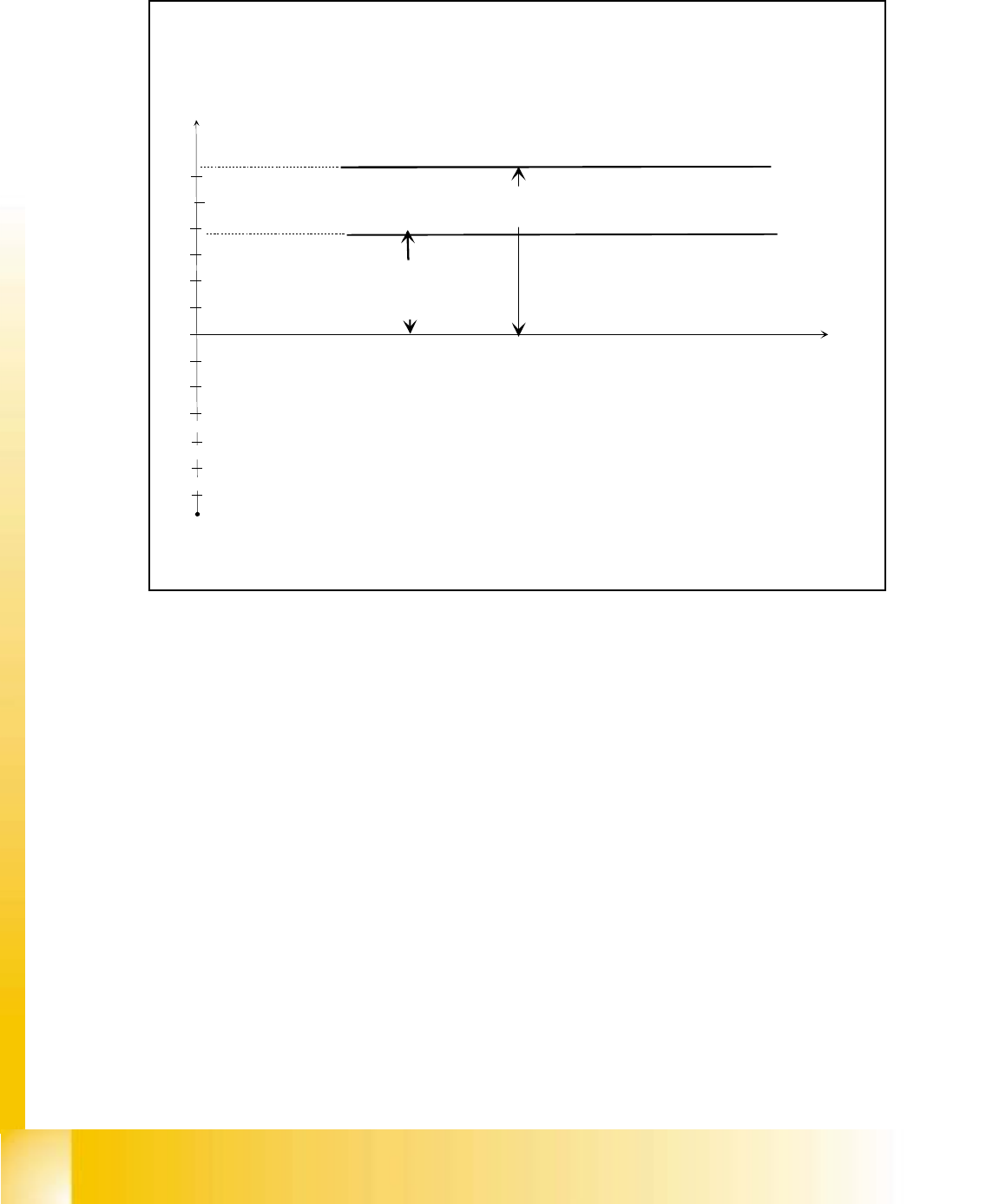
20.4.5.5 Air kiss at placement or at reject position
Fig. 20.4 - 7 Air kiss at placement or at reject position
1. Air kiss is applied at placement and reject positions to remove the component from the nozzle.
2. The placement pressure should be set to:
0.15 bar 71x/91x nozzles
0.20 bar 70x/90x nozzles 20
3. The reject pressure should be set to 0.25 bar.
200
160
120
80
40
0
t
240
Air kiss at placement position to
remove the vacuum in the nozzle
and to place the component
Air kiss at reject position to remove the vacuum
in the nozzle and to reject the component.
Pressure difference nozzle - inside -> environment
Student Guide HS-50 Advanced I 06/2002 Edition
20 Appendix
33
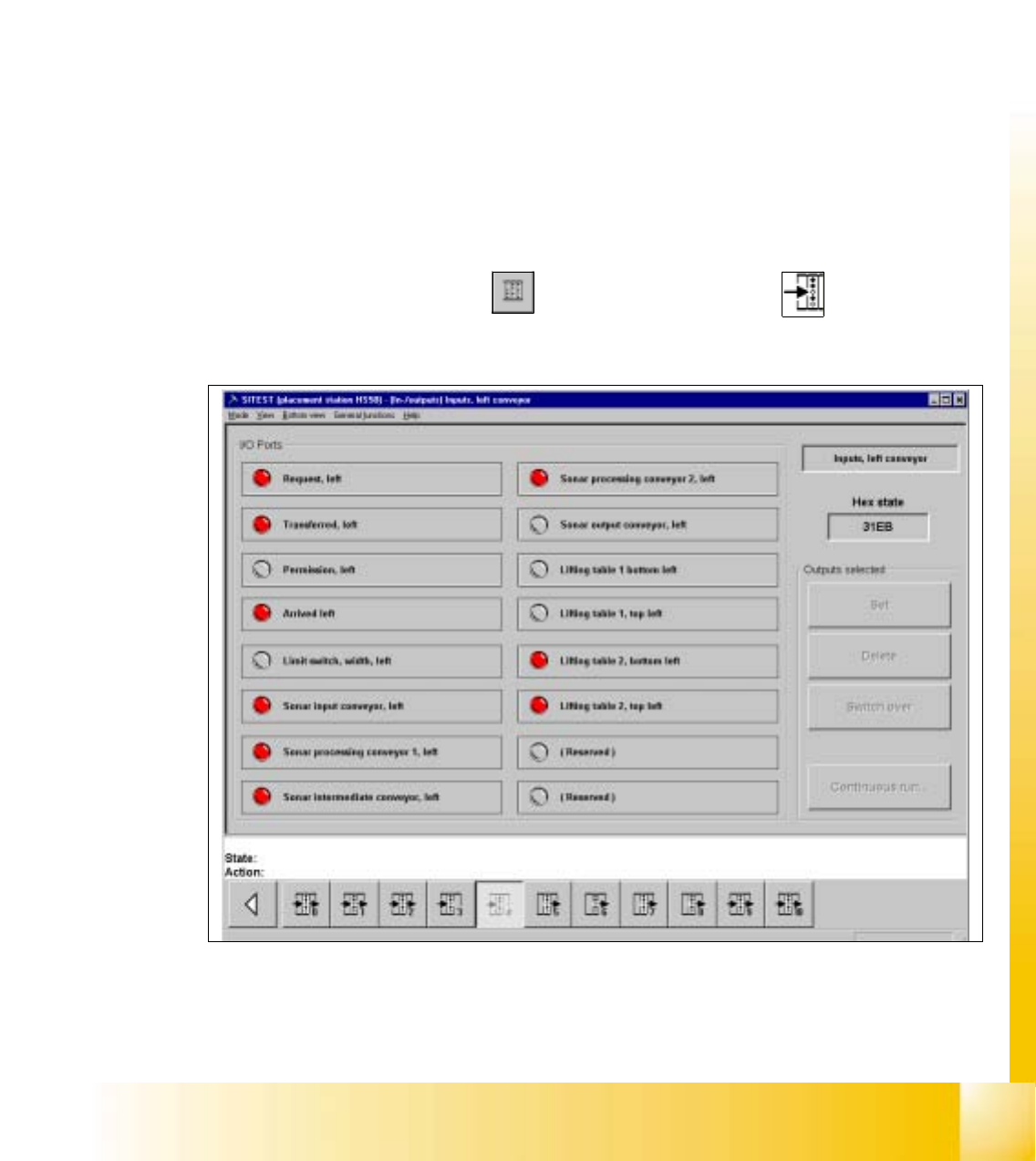
20.4.6 Testing Input / Output Functions
The following pages describe how it is possible to check the status of the inputs to the I/O cards
and how to set and test outputs. Following the description are pages that detail the I/O port and
bit assignments and their interconnection points in the left hand terminal strip. Here it is possible
to use a multimeter when troubleshooting to monitor the status of the hard wire signals to and from
the control elements. This helps to determine the source to a problem i.e. Whether it is a control
problem from the I/O card or a hard wire problem associated with the control element.
20.4.6.1 In-/Output Functions
The functions described in the following serve to selectively interrogate and activate individual bits
of the input and output cards of the SIPLACE machines and the wafflepack changer (only input
card).
Inputs 20
20
– In the main view click on the icon and then (if required) the icon to reach the
"Inputs" display.
20
Fig. 20.4 - 8 "Inputs" Display