HS50_advance_level 1_20200522_221201 (1).pdf - 第251页
Studen t Guide HS-50 A dvanced I 06/200 2 Edition 21 4 © PL EA 1 V GC Train ing Ver s i on Dec / 0 0 Ca libr ation of S IP LA C E HS- 50 Cali bration o f the compone nt camera With t hi s m enu we deter m ine: Ø the mech…
06/2002 Edition Student Guide HS-50 Advanced I
20
2
©
PL EA 1 V GC Training
Version Dec / 00
Calibration of SIPLACE HS-50
Calibration Steps
The different calibration steps are integrated in the SITEST test software.
With „calibrate heads and cameras“ the following sequence is executed automatically
Ø calibrate the PCB-camera
Ø calibrate the component-camera
Ø execute the segment offset I (above)
Ø execute the segment offset II (below) and the camera camera offset
Ø calibrate machine zero point
Ø calibrate nozzle changer
Ø calibrate the P&P (IC)-camera with P&P head the Flip-chip-camera
Additionally manual work
Ø calibrate the pick up height of nozzles
Ø calibrate coordinates at the PCB transport
Ø calibrate component table positions
Ø calibrate the coplanarity module (option)
Before starting calibration
Ø program Star axis zero point correction
3
©
PL EA 1 V GC Training
Version Dec / 00
Calibration of SIPLACE HS-50
Calibrate PCB camera
In this menu we determine:
Ø the mechanical Pixel size of the CCD-sensor
in µm.
This is calculated with the calibration
factors „Kalibrierfaktoren“ AX/BX/CX ...
Saved in REAL.MA
XU_Pixel / YU_Pixel. (in 11500nm)
Ø the camera center pixel.
Ø the angle of the CCD-Sensor according the
machine coordinate system.
Saved in REAL.MA
“Kamera_offset_Winkel“
Ø the camera offset is done with segment offset
above (II)
CCD Sensor angle to the
machine coordinate system
11,5 µm
11,5 µm
5800µm
5800µm
Student Guide HS-50 Advanced I 06/2002 Edition
21
4
©
PL EA 1 V GC Training
Version Dec / 00
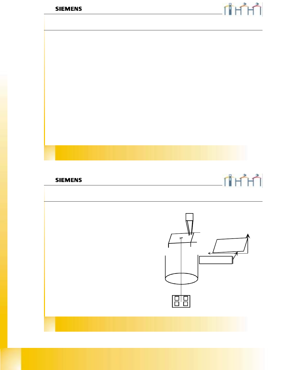
Calibration of SIPLACE HS-50
Calibration of the component camera
With this menu we determine:
Ø the mechanical Pixel size of the CCD-sensor in
µm.
This is calculated with the calibration factors
„Kalibrierfaktoren“ AX/BX/CX ...
Saved in REAL.MA
XU_Pixel / YU_Pixel. (in 24000 nm)
Ø the camera center pixel.
Ø the angle of the CCD-Sensor according the
turning level of the Placement Star.
Saved in REAL.MA „Kamera_offset_Winkel“
Ø the camera offset is set to Zero (because the
camera center is the reference for calibrations).
Saved in REAL.MA
„Kamera_offset_X“/„Kamera_offset_Y“
49,2 µm
49,2 µm
24000µm
24000µm
CCD Sensor angle
refering to the turning
level of the
placement star
5
©
PL EA 1 V GC Training
Version Dec / 00
Calibration of SIPLACE HS-50
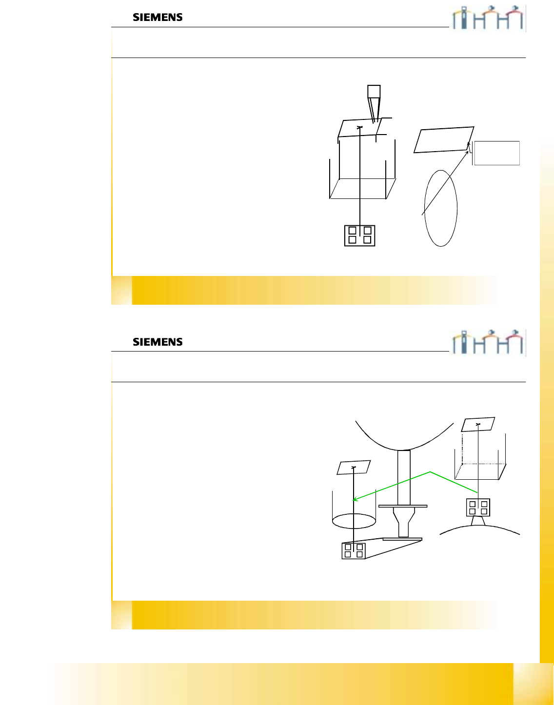
Segment offset II
The sequence at segment offset bottom / II is:
Ø We center the actual calibration tool position
with the PCB camera. Then we pick it up
and center it optically in the component
camera. The moving distance and the com-
ponent offset is taken for the result.
Ø With segment number 1 we calculate the
distance between the two camera centers;
called (RV-head) camera (PCB) camera
offset. This is saved in REAL.MA in the data
bloc of the PCB camera.
KAMERA_OFFSET_X
KAMERA_OFFSET_Y.
Ø All other segments get an OFFSET to this
segment 1;called segment offset II of this
segment .
Ø This is saved in PIP_OFF.MA file
06/2002 Edition Student Guide HS-50 Advanced I
22
6
©
PL EA 1 V GC Training
Version Dec / 00
Calibration of SIPLACE HS-50
Pcb camera - component camera offset
With segment number 1 we calibrate the distance
between component -and PCB-camera center;
called (RV-head) camera - (PCB) camera offset.
The machine center optically PCB camera the
calibration tool in the “tool pocket”. This
calibration tool is picked up with segment number
1 and optically centered in (RV) component
camera.
The travel distance of PCB camera from the
measured tool position to the measured actual tool
center position is measured.
This measured distance is set for the camera -
camera distance. There is not maximum limit set
for.
The component camera center is set for the
reference position.
OFFSET of the
cameras
7
©
PL EA 1 V GC Training
Version Dec / 00
Calibration of SIPLACE HS-50
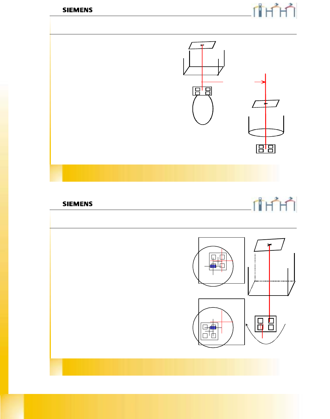
Segment offset I
0°
180°
With this menu we determine:
Ø the mechanical distance between center of the
component camera to the center of the turning axis
of the segment in µm.
This is calculated with a 180° turning of the
calibration tool on the nozzle.
Saved in PIP_OFF.MA.
Ø Picture 1 segment with calibration tool in 0° under
the camera. DP station turn than in 90° steps and
on each angle this measurement is done.
Ø First measurement results from 0° and 180° taken
to calculate turning axis.
The plausibility check is done with
the results from 90° and 270°.
Ø Picture 2 segment with calibration tool in 180°
under the camera.