HS50_advance_level 1_20200522_221201 (1).pdf - 第46页
06/2002 E dition Studen t Guide H S-50 Advance d I 2 Ov erview 16 2. 3 Sect or 3 F ig. 2. 3 - 1 S ecto r 3, CA N bus ad apt er CAN bus adapter PC B ou tput si de Sect or 3 Sector 3 contains the CAN bus adapter for th e c…
Student Guide HS-50 Advanced I 06/2002 Edition
2 Overview
15
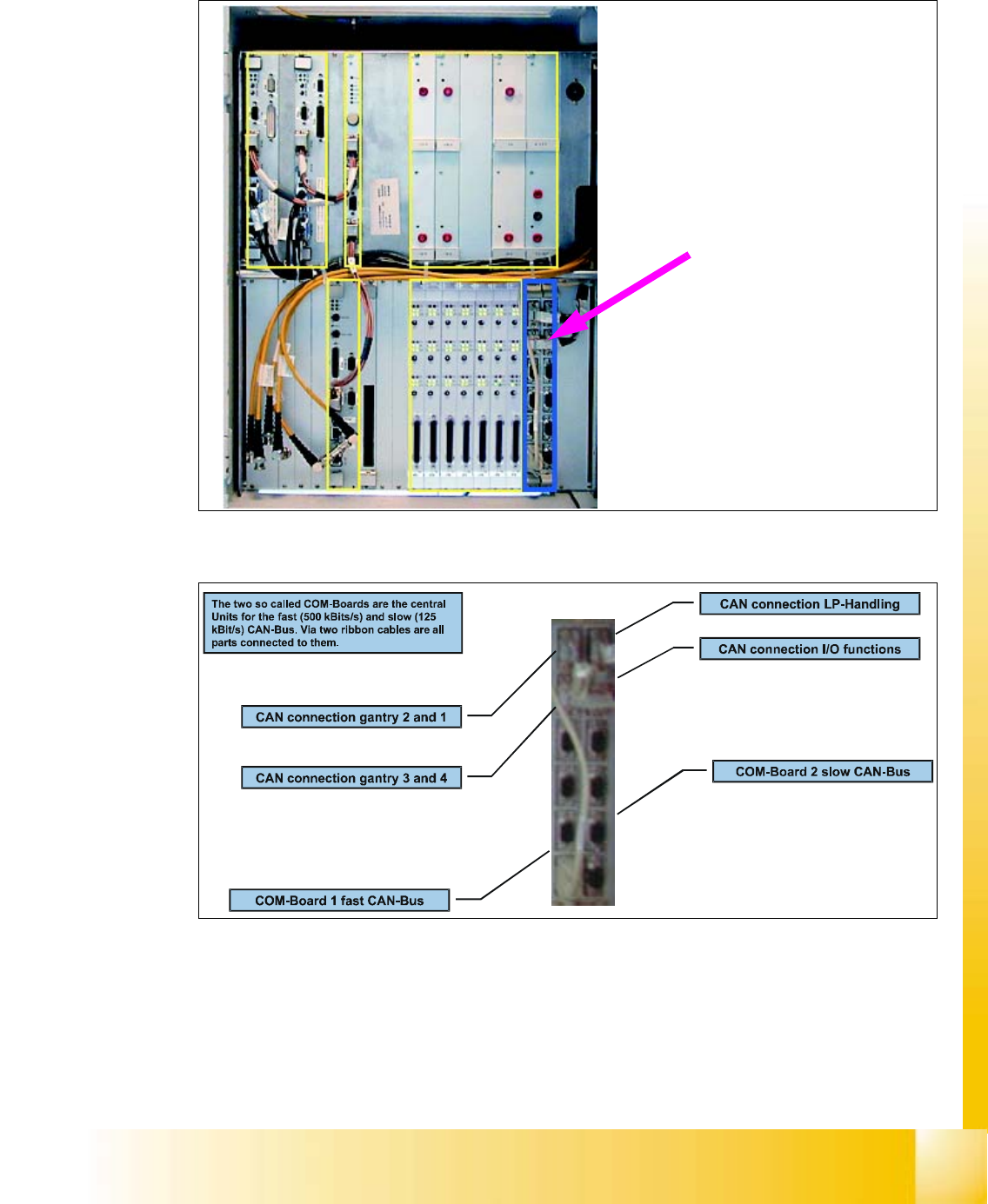
2.2.6 CAN-Bus Controller
Fig. 2.2 - 9 Control cage, CAN-Bus controller
Fig. 2.2 - 10 CAN-Bus Controller
The communication modules
provide an interface to the
CAN-Bus
06/2002 Edition Student Guide HS-50 Advanced I
2 Overview
16
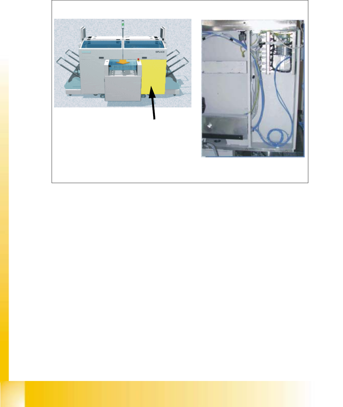
2.3 Sector 3
Fig. 2.3 - 1 Sector 3, CAN bus adapter
CAN bus adapterPCB output side
Sector 3
Sector 3 contains the CAN bus
adapter for the changeover table of gantry 3
Student Guide HS-50 Advanced I 06/2002 Edition
2 Overview
17
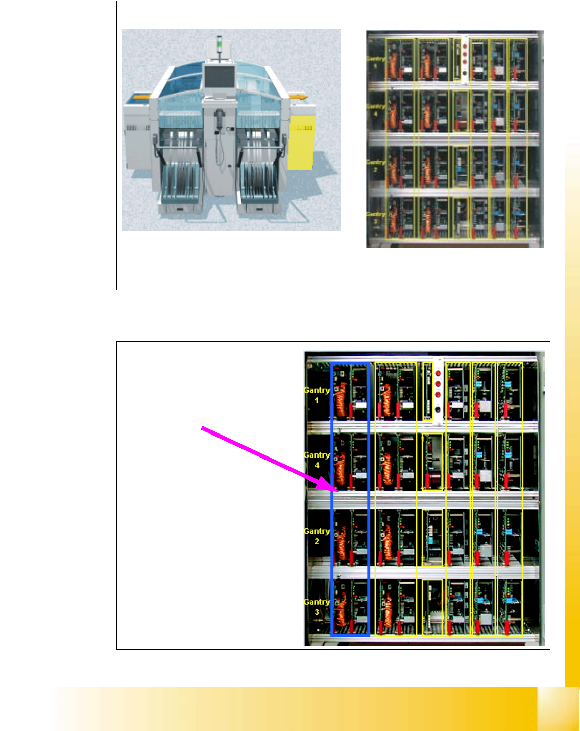
2.4 Servo Cage
Fig. 2.4 - 1 Servo unit
2.4.1 X-Axes
Fig. 2.4 - 2 Servo cage, X-axes
Right view (operator controls) Servo unit
The servo unit houses the servo cards for driving the
individual axes
X-axes Servo cards and brakes